Discharge spout for flexible bags

a discharge spout and flexible technology, applied in the field of flexible bags, can solve the problems of difficult to obtain a satisfactory finish, risk of damaging the elements of the discharge spout located near the tube, and not optimal with respect, so as to reduce the thickness of the tube wall, improve the sealing quality, and facilitate the centered position of the tub

Inactive Publication Date: 2011-06-23
VOLPAK
View PDF10 Cites 20 Cited by
  • Summary
  • Abstract
  • Description
  • Claims
  • Application Information

AI Technical Summary

Benefits of technology

[0014]This progressive sealing process, from the middle area toward the two ends of the tube, makes it considerably easier to maintain a centered position of the tube with respect to the jaws. Furthermore, the sealing is performed progressively and homogenously along the tube, whereby the end sealing quality is improved.
[0015]In addition to these supplementary advantages, the sealing spout according to the invention preserves the advantages of the discharge spout described in the mentioned document ES2300230A1: the melted plastic material is prevented from flowing over the outer edge of the sealing surface (as occurs with discharge spouts having a tube with a surface parallel to the axis of the tube) and the final shape of a flexible bag provided with the discharge spout according to the invention is improved.
[0016]Furthermore, this particular geometry of the outer surface of the tube according to the invention allows considerably reducing the thickness of the wall of the tube, whereby reducing the amount of plastic material necessary to manufacture the discharge spout. In fact, the preferred embodiments of the invention are characterized in that the wall forming the tube has throughout its entire extent, without including the flaps, a thickness less than or equal to one millimeter.
[0017]With respect to the shape of the tube in cross section, i.e., sectioned by a plane orthogonal to the longitudinal direction of the tube, several configurations can be provided, such as for example an ellipse shape or an ogive shape. However, for the purpose of making the sealing process easier, the outer surface of the tube preferably has, in a cross section according to a plane orthogonal to the axis of the tube, a circular shape.
[0018]In several optimal embodiments, which provide the best results with respect to the easiness of the sealing operation and to the sealing quality obtained, said middle area is in a centered position with respect to said two side sections. The distance occupied by said middle area, in the axial direction of said tube, is preferably less than or equal to one millimeter. As a result of this dimensional feature, the surface in which the material is initially melted is narrow, whereby the melted material flows more readily toward the two side sections on both sides of said middle area. In a particularly advantageous embodiment, the middle area is formed by the line of intersection between the two side sections, i.e., said middle area is substantially lacking thickness. The applicant has found that this particular configuration, with the middle area formed by a line without thickness, does not significantly affect the ease of centering the jaws because the initial melting is quick, an initial gripping area with sufficient thickness to assure centering being obtained in very little time. In contrast, the aforementioned advantage consisting of improving the creep of the melted material toward the two side sections is enhanced.

Problems solved by technology

A difficulty of this process is that due to the pressure exerted by the jaws, it is difficult to prevent the melted plastic material from flowing over the borders of the sealing surface, whereby it is difficult to obtain a satisfactory finish.
Furthermore, if the plastic material flows over the upper edge, it runs the risk of damaging the elements of the discharge spout which are located near the tube, for example the elements forming the sealing system which these discharge spouts are usually provided with.
Although this solution disclosed in document ES2300230A1 satisfactorily solves the drawbacks discussed above, it is not optimal with respect to the difficulty of developing an automated sealing process, nor with respect to the sealing quality obtained.

Method used


Image

  • Discharge spout for flexible bags
  • Discharge spout for flexible bags
  • Discharge spout for flexible bags

Examples


Embodiment Construction

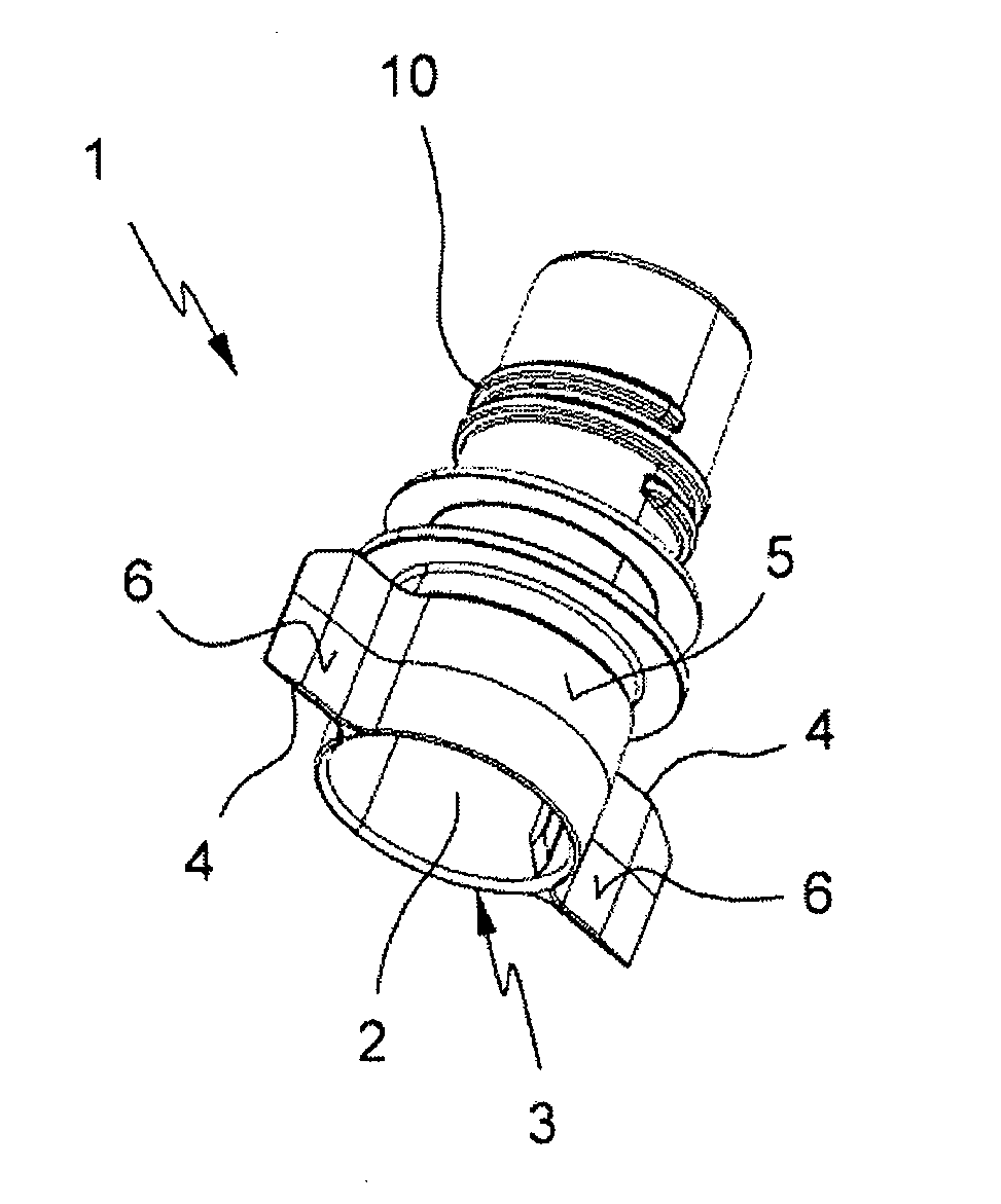
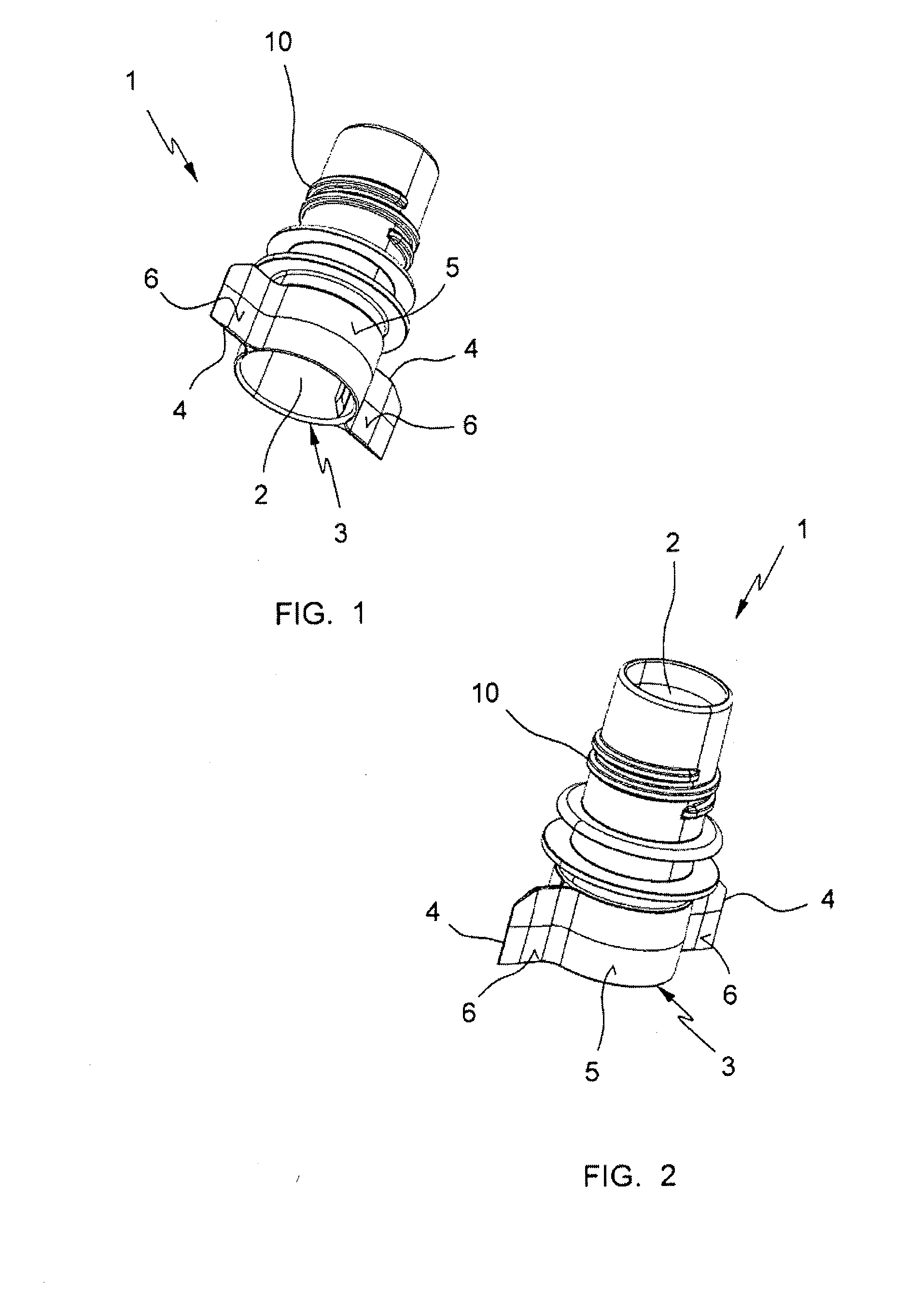
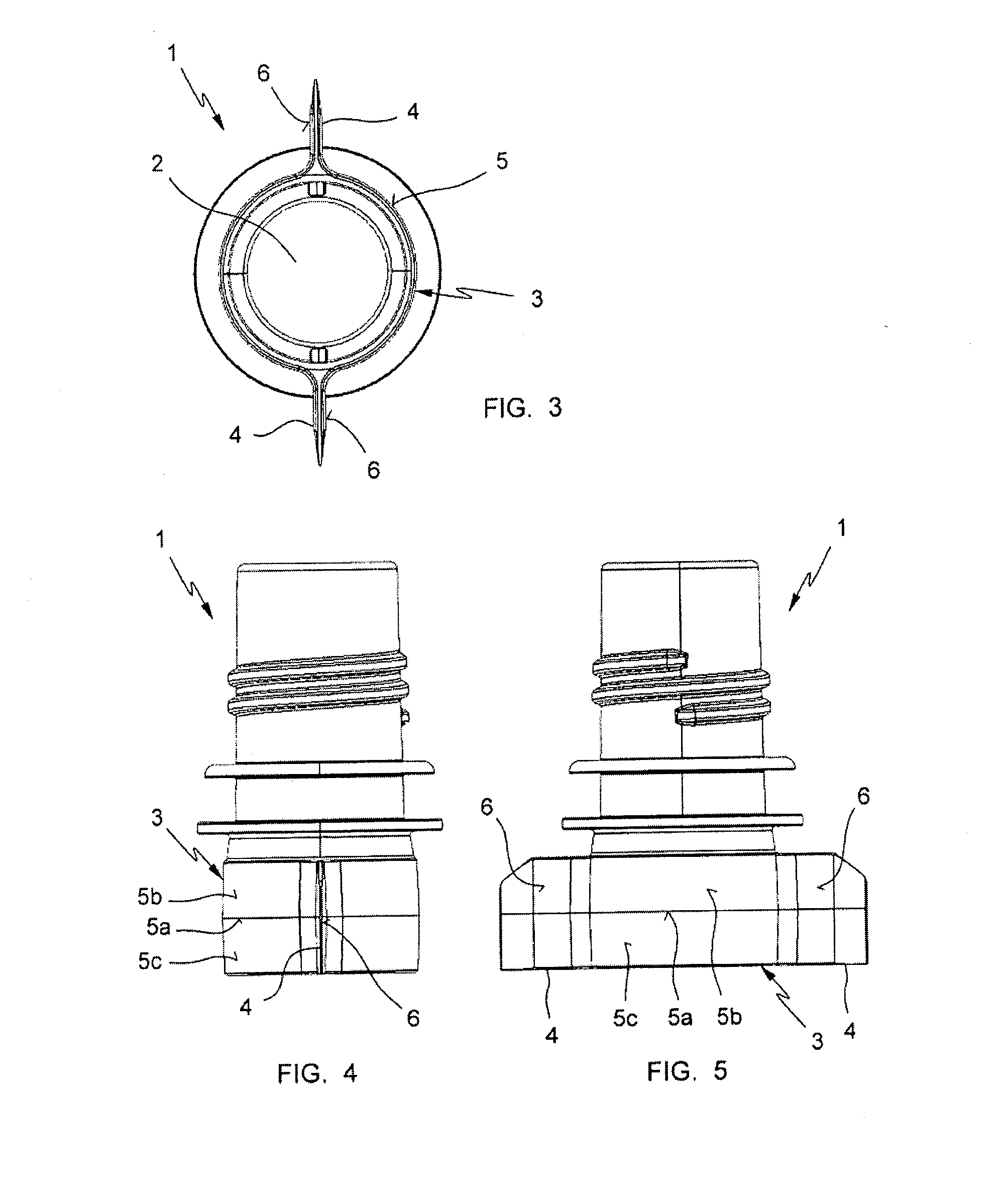
[0025]FIG. 1 a 10 show a preferred, non-limiting embodiment of the discharge spout according to the invention. The closure cap which is coupled to the discharge spout has not been depicted in the drawings because the configuration of the closure cap is irrelevant for the purposes of the present invention and the design thereof involves no difficulty whatsoever for a person skilled in the art. As can be seen in the drawings, the discharge spout 1 is provided with a thread 10 for the screw-on coupling of the closure cap. However, any other type of coupling for the closure cap can be provided, such as for example a bayonet-type coupling, without affecting the essence of the invention.

[0026]The discharge spout 1 according to the invention is specifically designed to be applied to a flexible bag (not depicted) known as a pouch and which are usually intended to contain a fluid or granulated product. As is known by a person skilled in the art, these pouch-type bags are plastic bags which a...


PUM

PropertyMeasurementUnit
thicknessaaaaaaaaaa
distanceaaaaaaaaaa
thicknessaaaaaaaaaa

Abstract

The invention relates to a discharge spout for flexible bags, of the type comprising a rigid plastic body forming a discharge passage and having a tube (3) intended to be inserted between two walls of a flexible bag and joined to such walls by means of sealing. The tube (3) has a smooth outer surface and two opposite flat flaps (4) extending externally in a mid-plane of said tube (3). The outer surface of the tube (3) forms, together with the surface (6) of the flat flaps (4), a sealing surface. The outer surface of the tube (3) is a dished surface in the axial direction of the tube, and it has a middle area (5a) in which the distance to the axis (7) of the tube is maximum, separating two side sections (5b, 5c) in which the distance to the axis (7) is decreasing toward the ends of the tube.

Description

FIELD OF THE INVENTION[0001]The invention is comprised in the field of flexible bags of the type known as a pouch and generally used to contain fluids or granules. These bags are provided with a rigid discharge spout which is sealed between the two walls forming the flexible bag.[0002]The invention more specifically relates to a discharge spout for flexible bags of the type comprising a rigid plastic body forming a discharge passage and having a tube intended to be inserted between two walls of a flexible bag and being joined to such walls by means of sealing, said tube having a smooth outer surface and two opposite flat flaps extending externally in a mid-plane of said tube, said outer surface of the tube forming, together with the surface of said flat flaps, a sealing surface.STATE OF THE ART[0003]The discharge spouts referred to by the invention have the particularity that the mentioned outer surface of the tube which is sealed to the walls of the bag is smooth, in the sense that...

Claims


Application Information

Patent Timeline
Patent Type & Authority Applications(United States)
IPC IPC(8): B65D33/38
CPCB65D2575/583B65D75/5883B65D75/5861
Inventor BONET PEDROL, JAUME
Owner VOLPAK
Why Eureka
Try Eureka