
Magnet valve and driver assistance system

a technology of driver assistance and magnet valve, which is applied in the direction of valve details, valve arrangements, valve housings, etc., can solve the problems of complex and expensive production of the valve body, and achieve the effects of efficient calming of the flow, improved wear properties or sealing properties, and simple production of magnet valves

Inactive Publication Date: 2011-06-23
ROBERT BOSCH GMBH
View PDF7 Cites 1 Cited by
  • Summary
  • Abstract
  • Description
  • Claims
  • Application Information

AI Technical Summary

Benefits of technology

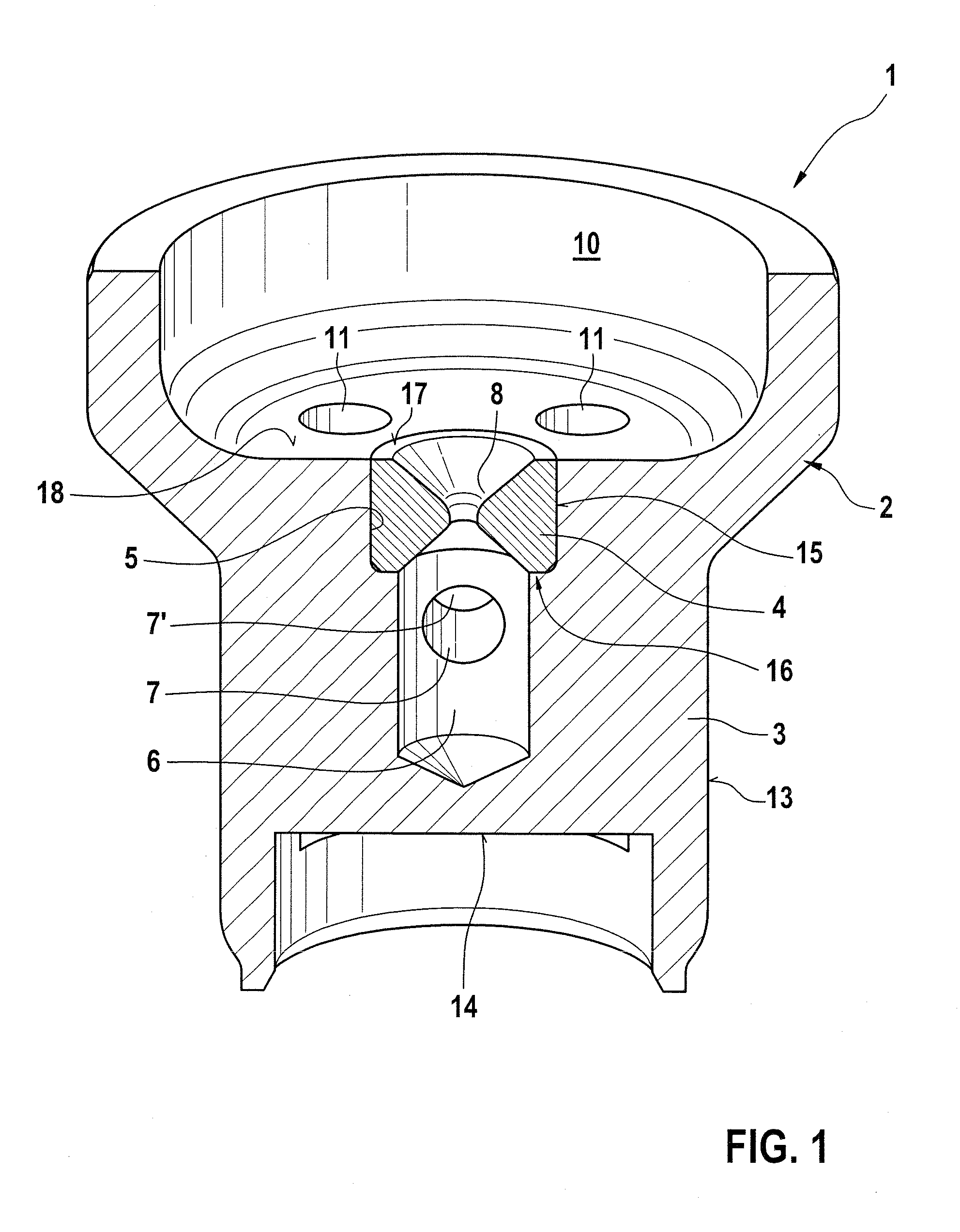
[0008]A refinement of the invention provides that the insert part and / or the base body has or together form at least one flow conduit between a fluid chamber, fluidically communicating with the outlet conduit, and the outlet conduit. The fluid chamber, which is present in the magnet valve or is embodied by the valve body, is in fluidic communication with the outlet conduit. Thus fluid flowing into the fluid chamber can reach the outlet conduit and through it can flow out of the magnet valve. For establishing this fluidic communication, the flow conduit or a flow line is provided. The flow conduit is for instance in the form of a conduit on or in the insert part or the base body of the valve body. Alternatively, the insert part and the base body can also jointly form the flow conduit. The flow conduit can also be designed in such a way that after flowing through the valve seat, the flow is calmed in the flow conduit before the fluid emerges from the magnet valve through the outlet conduit. That is, the flow conduit is embodied virtually in the form of a calming chamber or calming line.
[0007]A refinement of the invention provides that the insert part at least in some regions has the inlet conduit and / or the outlet conduit or is embodied together with a base body of the valve body. Typically, there is a permanent fluidic communication between either the inlet conduit or the outlet conduit and the valve seat. Accordingly, the insert part, which forms the valve seat, must be designed also for establishing the fluidic communication. For that purpose, the inlet conduit and / or the outlet conduit are located at least in some regions in the insert part. In an alternative embodiment, it may be provided that the inlet conduit or the outlet conduit is formed jointly by the insert part and by the base body of the valve body. For example, the inlet conduit or the outlet conduit can be defined in the circumferential direction by an outer face of the insert part and an inner face of the base body.
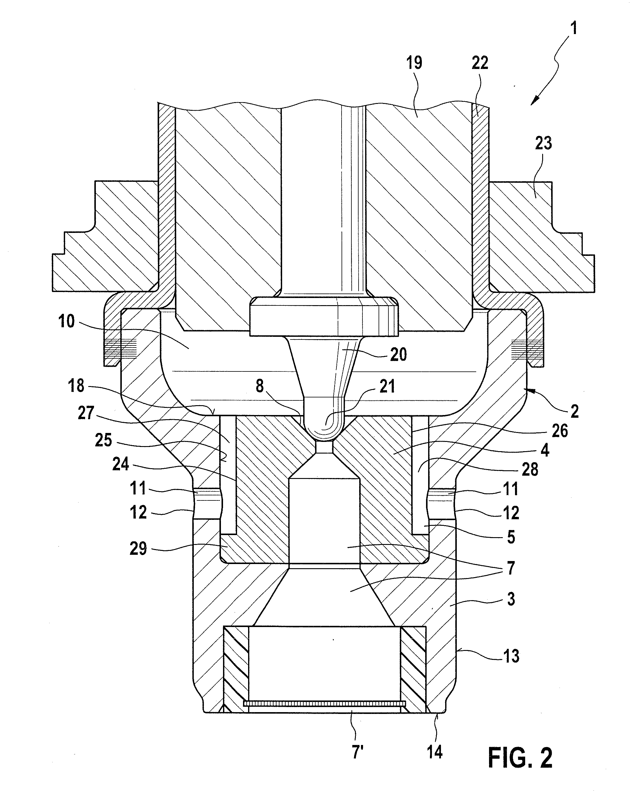
[0010]A refinement of the invention provides that the flow conduit is embodied, in particular in the form of an annular gap, between an inner face of the base body and an outer face of the insert part. The inner and outer faces are spaced apart from one another in such a way that the flow conduit is located between them. As already explained above, for that purpose the setback can be present on the insert part or the base body of the valve body. It is especially advantageous if the flow conduit completely embraces the base body in the circumferential direction. In that case, the flow conduit is in the form of the annular gap. With such an embodiment of the magnet valve, especially efficient calming of the flow is achieved, before the fluid exits the magnet valve through the outlet conduit.
[0011]A refinement of the invention provides that the insert part has a base for securing to the base body. The base preferably has larger dimensions than other regions of the insert part. For instance, the insert part can have the setback, so that in at least one region it has smaller dimensions than the receptacle region of the valve body. The base is also provided, in which the insert part has the same or slightly larger dimensions than the receptacle region. Thus the insert part can be securely held in the receptacle region by means of the base, for instance by press-fitting of the base into the receptacle region. The base is disposed such that the flow conduit—if provided—is not blocked by it.
[0012]A refinement of the invention provides that the base defines the flow conduit between the fluid chamber and the outlet conduit. Accordingly, the base adjoins the flow conduit that is present between the fluid chamber and the outlet conduit. The side of the base toward the flow conduit can be designed in a streamlined way, for instance extending in inclined or curved fashion in the direction of the outlet conduit. In this way, an especially favorable course of the flow with only slight pressure losses between the fluid chamber and the outlet conduit is attained.
[0013]A refinement of the invention provides that the insert part is secured to the base body in form-locking, force-locking and / or material-locking fashion. In principle, the insert part can be held on the base body in an arbitrary way. One simple, economical possibility is to embody the insert part as a press-fitted part, so that after the production of the base body it is press-fitted into the receptacle region and is held there in force-locking fashion. Alternatively or in addition, it is understood that a material-locking or form-locking connection may be provided. A material-locking connection is realized for instance by means of an adhesive.

Problems solved by technology

This makes the production of the valve body complicated and expensive.

Method used


Image

  • Magnet valve and driver assistance system
  • Magnet valve and driver assistance system
  • Magnet valve and driver assistance system

Examples


Embodiment Construction

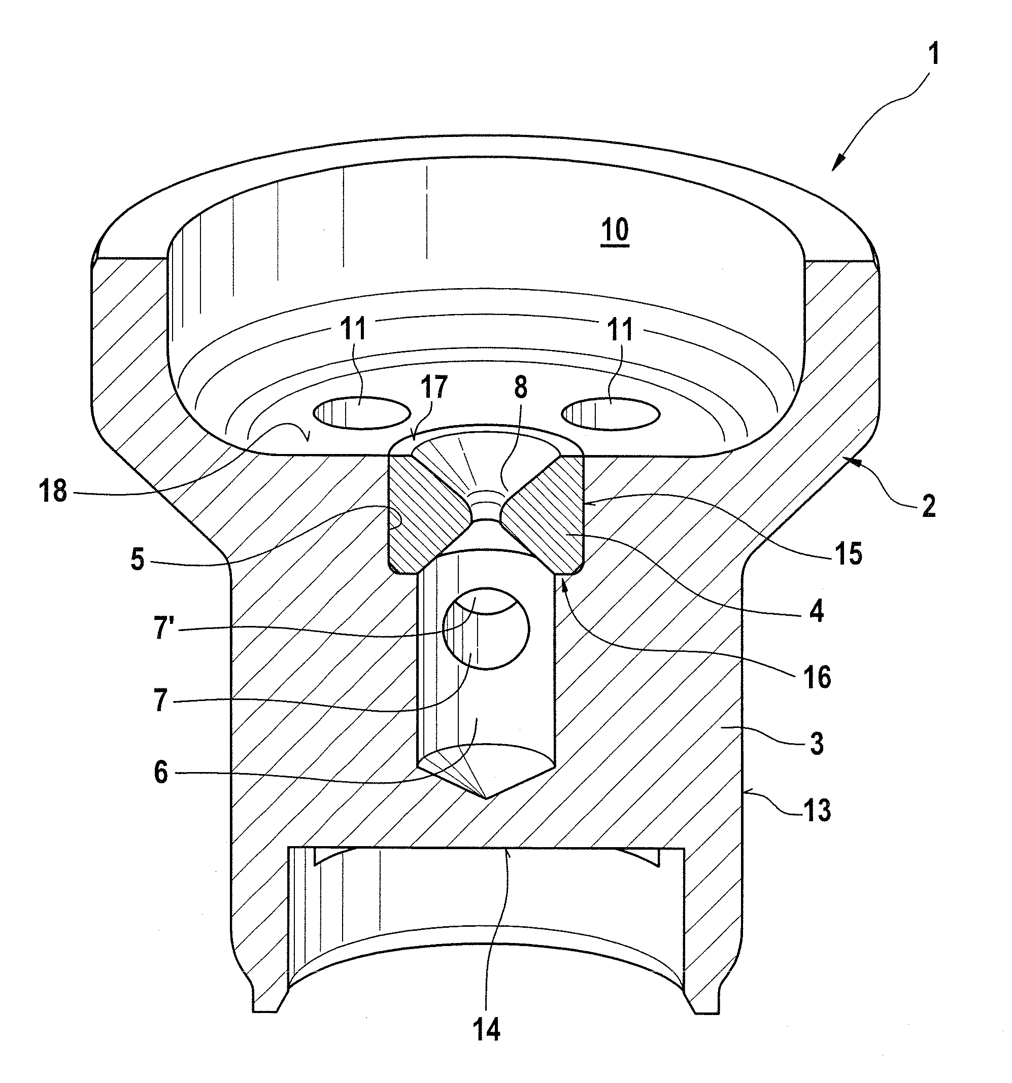
[0021]FIG. 1 shows a cross section of a region of a magnet valve 1, in which only one valve body 2 is shown. The valve body 2 comprises a base body 3 and an insert part 4, which insert part is disposed in a receptacle region 5 of the base body 3 or of the valve body 2. A riser conduit 6 is embodied in the valve body 2 and is in fluidic communication via an inlet conduit 7 with at least one inlet port 7′. Via the inlet port 7′, the magnet valve 1 can be supplied with a fluid. The fluid supplied through the inlet port 7′ flows through a valve seat 8, which is embodied by the insert part 4, when the insert part is opened by a sealing element, not shown here. On the side of the valve seat 8 remote from the riser conduit 6, a fluid chamber 10 is provided, which is embodied in at least some regions by the valve body 2. Moreover, at least one outlet conduit 11, which discharges into the fluid chamber 10, is provided in the valve body 2. There is a permanent fluidic communication between th...


PUM


Abstract

The invention relates to a magnet valve having a valve body, in which at least one inlet conduit and / or at least one outlet conduit of the magnet valve is provided in at least some regions in the valve body. The inlet conduit and / or outlet conduit are in fluidic communication with a valve seat of the magnet valve. According to the invention, the valve body is provided with a receptacle region, in which an insert part embodying the valve seat is disposed. The invention also relates to a driver assistance system having such a magnet valve.

Description

CROSS-REFERENCE TO RELATED APPLICATION[0001]This application is based on German Patent Application 10 2009 060 294.1 filed on Dec. 23, 2009.BACKGROUND OF THE INVENTION[0002]1. Field of the Invention[0003]The invention relates to a magnet valve having a valve body, in which at least one inlet conduit and / or at least one outlet conduit of the magnet valve is provided in at least some regions in the valve body, and the inlet conduit and / or outlet conduit are in fluidic communication with a valve seat of the magnet valve. The invention also relates to a driver assistance system.[0004]2. Description of the Prior Art[0005]Magnet valves of the type defined at the outset are known from the prior art. They are used for instance for ABS, TC or ESP systems. Typically, they are magnet valves with a radial oncoming flow that are closed when without current and are continuously variable. However, still other embodiments of the magnet valve are feasible, for instance being open when without curren...

Claims


Application Information

Patent Timeline
Patent Type & Authority Applications(United States)
IPC IPC(8): F16K31/02
CPCB60T8/3615F16K27/029F16K31/0665
Inventor KURZ, EDGAR
Owner ROBERT BOSCH GMBH
Learn More