Apparatus and method for camera parameter calibration

Inactive Publication Date: 2011-06-23
UDP TECH +1
View PDF3 Cites 37 Cited by
  • Summary
  • Abstract
  • Description
  • Claims
  • Application Information

AI Technical Summary

Benefits of technology

[0023]The camera parameter calibration apparatus and method according to an embodiment of the present invention has an advantage of correct image analysis that it is capable of increasing accuracy of information of measurement through an image only with an intuitive interface manipulation, without taking a time-consuming and incorrect actual measurement procedure, by determining parameters of the space model corresponding to the image by displaying a 3D space model corresponding to a real space of the image on the image and changing and adjusting visual point parameters such that the 3D space model matches the display image, and regarding the determined parameters of the space model as camera parameters of the image.
[0024]The camera parameter calibration apparatus and method according to an embodiment of the present invention has an advantage that it is capable of simply and offhandedly setting parameters for mapping an image to a real space by adjusting a 3D model object to correspond to a similar object in an real image by displaying the 3D model object on the image, allowing the 3D model object to be moved around on the ground and varying the representation of

Problems solved by technology

In particular, a space mapping which allows correct measurement of size is essential for precise image analysis, however, for a camera image obtained by projecting a portion of 3-dimensional (3D) space onto a 2-dimensional (2D) space, it is difficult to map a 2D image to a 3D space model without additional information.
However, for such a space model configuration, since the installation position and tilt angle of the camera must be actually measured, it is not easy to calculate the height and tilt angle of the camera and reliability of calculated actual measurement values is not high due to irregularity of ground and so on.
In addition, for FOV, if an auto-focusing function or a zooming function is used for the FOV, it is diffi

Method used


Image

  • Apparatus and method for camera parameter calibration
  • Apparatus and method for camera parameter calibration
  • Apparatus and method for camera parameter calibration

Examples


Embodiment Construction

[0037]Hereinafter, the present invention will be described in detail by way of preferred embodiments with reference to the accompanying drawings.

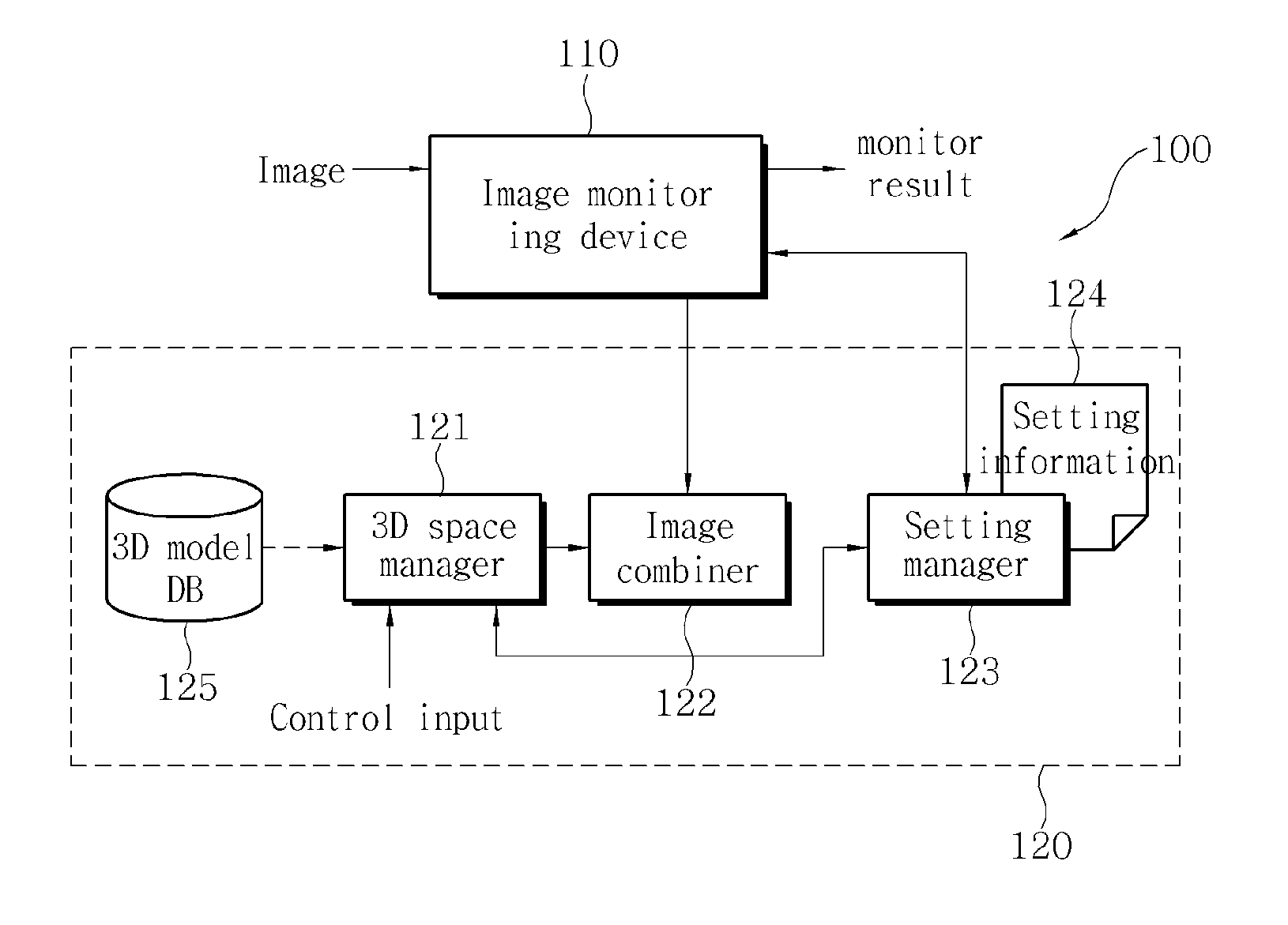
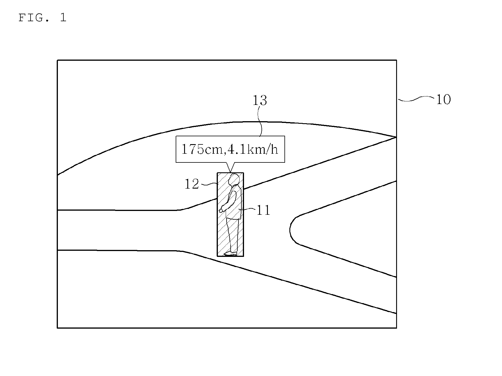
[0038]FIG. 3 explains parameters required for a space modeling for mapping a 2D image to a 3D space, where a camera 30 is a visual point for acquiring an image as well as a visual point in a corresponding space modeling.

[0039]Accordingly, 2D mapping information on a space obtained through the camera 30 can be mathematically modeled through parameters such as height (H), tilt angle (θt) and field of view (θf) of the camera 30 with respect to the ground and vice versa, so if the parameters can be correctly known, it is possible to model a real 3D space from a 2D image and map the 2D image to the 3D space.

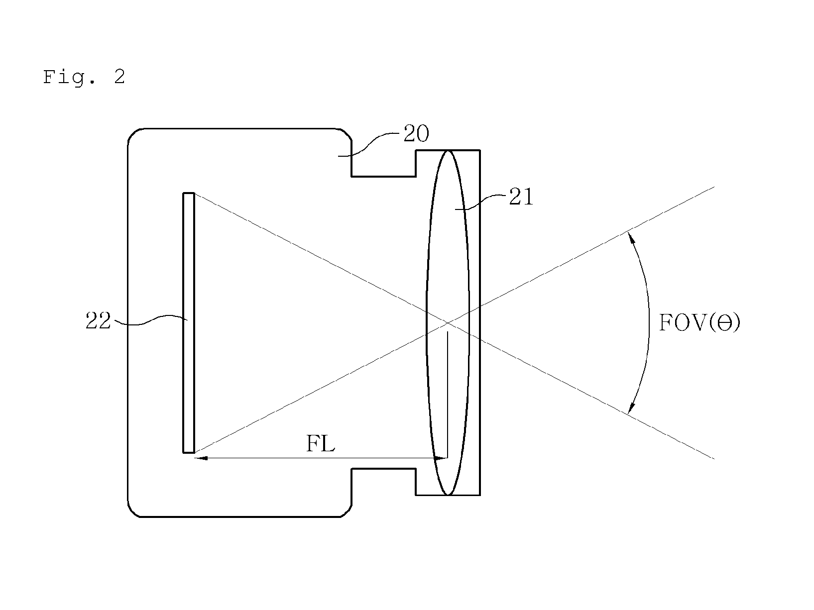
[0040]Here, the field of view (FOV) of the camera may be obtained using lens characteristics, focal length and so on and thus may be replaced with such lens characteristics or focal length.

[0041]FIG. 4 shows a configuration of a camera calibr...


PUM


Abstract

The present invention provides an apparatus and method for camera parameter calibration which is capable of easily and simply setting physical and optical characteristic parameters of a camera in order to acquire information on actual measurement of an image provided through the camera with high accuracy. The camera parameter calibration apparatus and method has an advantage of correct image analysis that it is capable of increasing accuracy of information of measurement through an image only with an intuitive interface manipulation, without taking a time-consuming and incorrect actual measurement procedure, by determining parameters of the space model corresponding to the image by displaying a 3D space model corresponding to a real space of the image on the image and changing and adjusting visual point parameters such that the 3D space model matches the display image, and regarding the determined parameters of the space model as camera parameters of the image.

Description

CROSS-REFERENCE TO RELATED APPLICATION[0001]This application claims the benefit of Korean Application No. 10-2009-0126014, filed on Dec. 17, 2009, with the Korean Intellectual Property Office, the disclosure of which is incorporated herein by reference.BACKGROUND OF THE INVENTION[0002]1. Field of the Invention[0003]The present invention relates to an apparatus and method for camera parameter calibration, and more particularly, to an apparatus and method for camera parameter calibration which is capable of easily and simply setting physical and optical characteristic parameters of a camera in order to acquire information on the actual size of objects within an image provided through the camera with high accuracy.[0004]2. Description of the Related Art[0005]With recent rapid development of imaging technologies for security, vision recognition and so on, there have been developed various image processing techniques for analyzing contents of an image obtained through a camera, recognizi...

Claims


Application Information

Patent Timeline
IPC IPC(8): H04N13/02
CPCG06T7/0018G06T2207/20092H04N5/23216H04N17/002H04N13/004G06T7/80H04N13/156H04N7/18H04N13/00H04N5/262H04N23/62
Inventor ECCLES, ETIENNEWHITE, BENTHIEL, GEOFFAHN, JUNG KEUN
Owner UDP TECH
Why Eureka
Try Eureka