System for providing two position zoom-focus

a technology of optical system and two-position zoom, which is applied in the field of video inspection, can solve the problems of inspector's inability to relocate the specific site of interest, difficulty in maintaining sufficient image brightness, and each tip providing a discrete field of view and focus distance chang

Active Publication Date: 2011-06-23
GE INSPECTION TECH LP
View PDF8 Cites 6 Cited by
  • Summary
  • Abstract
  • Description
  • Claims
  • Application Information

AI Technical Summary

Benefits of technology

[0008]An optical system for imaging target objects is disclosed, comprising a rail upon which a focus lens cell and a zoom lens cell are moveably mounted, the focus lens cell comprising at least one focus lens and a primary aperture that limits the amount alight incident on the focus lens, wherein the focus lens cell has a first focus position on the rail and a second focus position on the rail, and wherein the first focus position has a different depth of field than the second focus position, the zoom lens cell comprising at least one zoom lens, wherein the zoom lens cell has a first zoom position on the rail and a second zoom position on the rail, wherein the first zoom position has a different magnification than the second zoom position, a secondary aperture proximate the focus lens cell, wherein the secondary aperture is moveable in front of the focus lens cell, wherein the secondary aperture has a first aperture position and a second aperture position, and wherein the first aperture position allows a different amount of light to be incident on the focus lens than the second aperture position, and a lens movement mechanism that causes movement of the focus lens cell axially along the rail, wherein the lens movement mechanism moves the focus lens cell from the second focus position to the first focus position axially along the rail causing movement of the secondary aperture from the second aperture position to the first aperture position and movement of the zoom lens cell from the second zoom position to the first zoom position axially along the rail to change the depth of field, the magnification, and the amount of light incident on the focus lens.

Problems solved by technology

When the inspection device is located further away from a given inspection target maintaining sufficient image brightness may be problematic.
The drawback of this arrangement is that each tip provides a discrete field of view and focus distance change.
This can be a time consuming process, and can result in the inspector's inability to relocate the specific site of interest.
However, such tips can be difficult for the inspector to use since the inspector must know at what distance to focus the tip before using it, and then subsequently be able to accurately set that focus.
Video inspection devices today generally lack an auto-focus mechanism and contain optical systems that are designed to have a fixed focal length with a large depth of field that is sufficient to produce adequate image quality over the typical range of inspection distances.
Having this fixed focal length results in all but a limited range of probe focus distances not having the best focus, image quality, contrast and resolution possible.
This inherently results in conflicting goals of achieving good image quality within an acceptable depth of field at close inspection distances while providing a clear, bright image at farther inspection distances.
The design of a video inspection system able to perform optical zooming, focus adjustment and aperture variation is constrained, in part, because of space limitations associated with narrow diameter inspection probes, and the inability to place an optical system capable of varying its focal length within the limited space of the probe.
Some devices attempt to provide optical zoom and focus adjustment capabilities using costly, complex optical arrangements consisting of numerous lenses and / or motors that are difficult to fit within an endoscope.
Although several existing video inspection devices offer a zooming capability, the zoom feature is typically that of a digital zoom, a method limited by the resolution provided by the charged coupled device (CCD) or imager.
Because of space limitations, the distal end of the video inspection device must be of a fixed rigid length.
In addition, the ability to operate the video inspection device in environments up to 80 degrees Celsius. such as a hot engine or turbine, is sometimes necessary and cost effective, as opposed to first waiting for the engine or turbine to cool down before performing the inspection.
Conventional zoom and focus systems employed in cameras outside of the video inspection device field are limited in their application to the video inspection field by their size and inability to operate in the extreme environments encountered in the inspection field.

Method used


Image

  • System for providing two position zoom-focus
  • System for providing two position zoom-focus
  • System for providing two position zoom-focus

Examples


Embodiment Construction

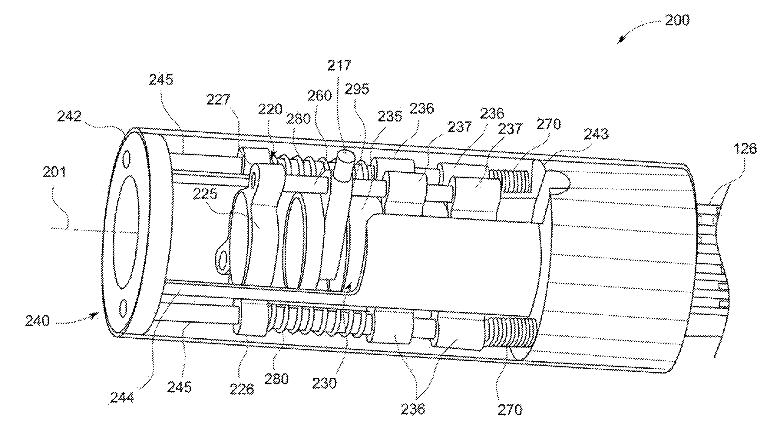
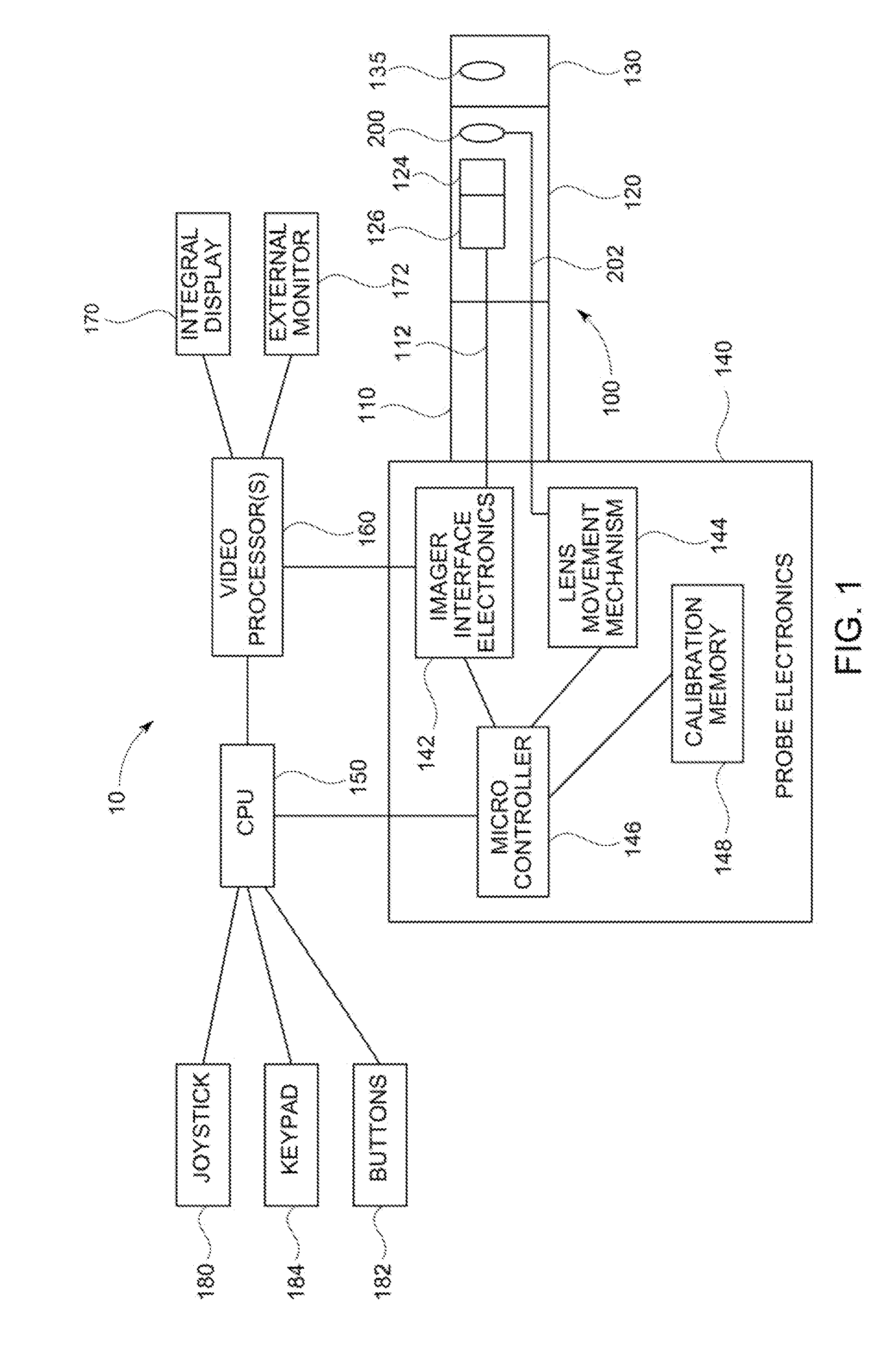
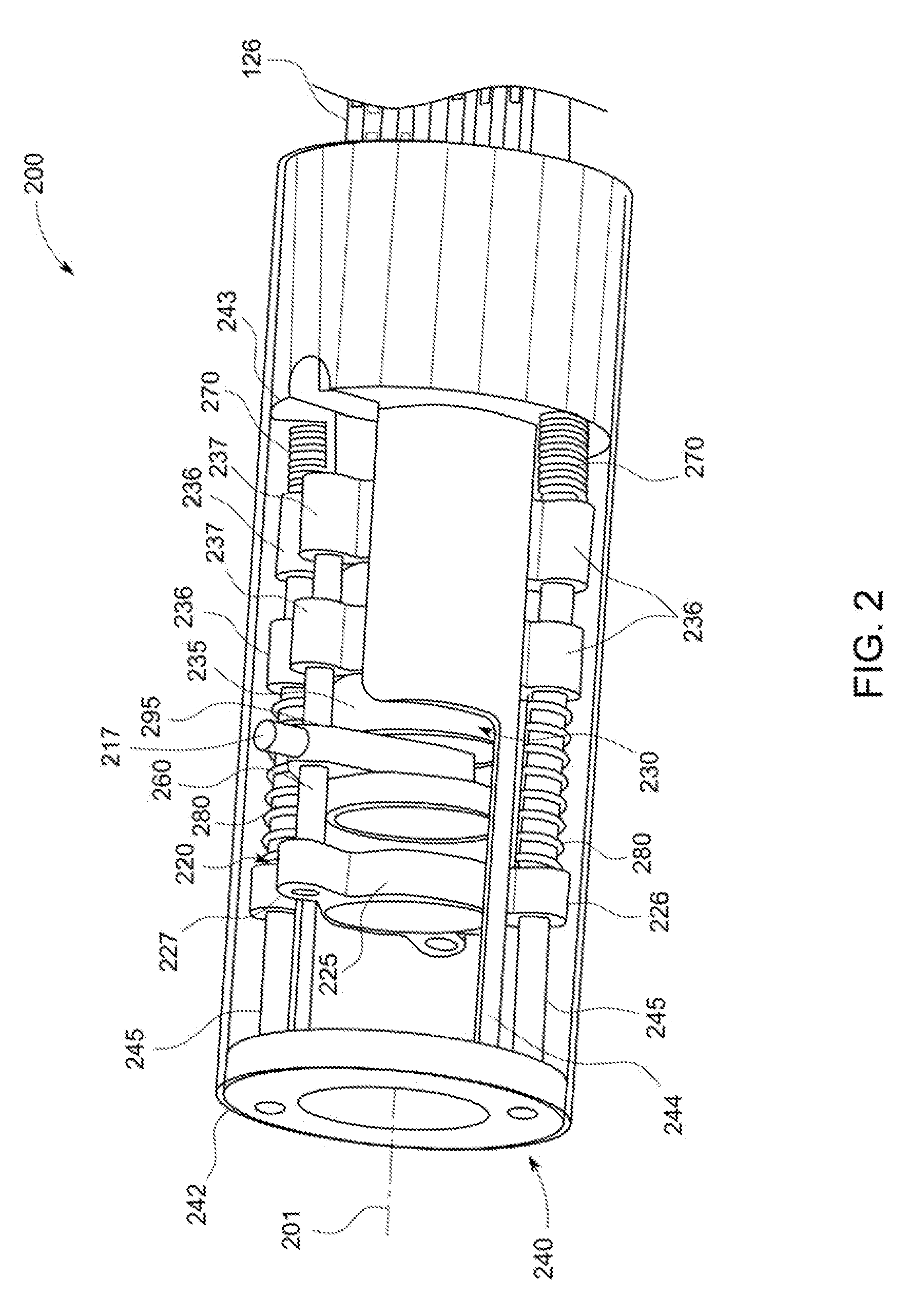
[0015]FIG. 1 illustrates an exemplar video inspection device 10 in one embodiment of the invention. Video inspection device 10 can include an elongated probe 100 comprising an insertion tube 110 and a head assembly 120 disposed at the distal end of the insertion tube 110. Insertion tube 110 can be a flexible, tubular section through which all interconnects between the head assembly 120 and probe electronics 140 are passed. Head assembly 120 can include zoom-focus module 200 for guiding and focusing light from the target object onto an imager 124. The imager 124 can be a solid state CCD or CMOS image sensor for obtaining an image of the target object.

[0016]A tip 130 can be placed on the distal end of the head assembly 120. The tip 130 can include tip viewing optics 135 (e.g., lenses, windows, or apertures) that work in conjunction with the zoom-focus module 200 to guide and focus light from the target object onto an imager 124. The tip 130 can also include illumination LEDs (not show...


PUM


Abstract

A system for providing a two-position zoom-focus capability in a video inspection device comprising, in one embodiment, a focus lens cell and primary aperture attached to a set of fixed rails and connected to a zoom lens cell. In one embodiment, the focus lens cell is moveable into a first position along the rails through activation of a proximally located lens movement mechanism, and moveable into a second position through relaxation of a tensioned focus spring. In one embodiment, movement of the focus lens cell between first and second focus positions causes movement of the zoom lens cell and a secondary aperture between corresponding first and second zoom and aperture positions to provide unmagnified and magnified images of a target object.

Description

BACKGROUND OF THE INVENTION[0001]The subject matter disclosed herein relates generally to video inspection, and more particularly to a two position zoom-focus optical system for video inspection devices.[0002]Video inspection devices, such as video endoscopes, can be used to inspect target objects to identify and analyze flaws and defects in the objects both during and after an inspection. Often times, inspections are performed in small environments such as inside aircraft engines and small pipes. Typically, these environments are poorly illuminated with the only source of light being the endoscope's own light source (e.g., a fiber optic bundle that transmits light from a proximally located lamp, LED or laser, or a distally located lamp or LED). In order for video inspection devices to be effective in maneuvering in these environments, they must be of small diameter, typically less than 10 mm, and exhibit a small distal rigid length, typically less than 20 mm, in order to navigate t...

Claims


Application Information

Patent Timeline
Patent Type & Authority Applications(United States)
IPC IPC(8): G02B7/10
CPCG02B23/2438G02B7/10
Inventor SCOTT, JOSHUA LYNNBENDALL, CLARK ALEXANDERCHILEK, THEODORE ALEXANDER
Owner GE INSPECTION TECH LP
Why Eureka
Try Eureka