Skating simulator

a simulator and skating technology, applied in the field of skating, can solve the problems of inability to replicate the biomechanically correct position of the ankle pronation and supination of the ankle seen in the simulator, and the individual's ability to bring his/her feet,

Active Publication Date: 2011-06-23
HALVER TERRENCE
View PDF23 Cites 38 Cited by
  • Summary
  • Abstract
  • Description
  • Claims
  • Application Information

AI Technical Summary

Problems solved by technology

Previous attempts to re-create the skating motion have met with mixed results.
When using a PLLMM it is not possible for the individual to bring his / her feet together at either end of the machine, or even bring his / her feet together even in the middle of the machine.
The pronation and supination of the ankle seen in these simulators does not replicate the bio-mechanically correct position of the ankle throughout the skating stride during skating on ice.
This unnatural movement of the ankle as the foot slides laterally can cause sore and / or bruised ankles or even serious injury.
Additionally this unnatural movement forced upon the ankle in previous devices limits training options, decreases the value of training, and decreases the likelihood the training will transfer to on-ice performance.

Method used


Image

  • Skating simulator
  • Skating simulator
  • Skating simulator

Examples


first embodiment

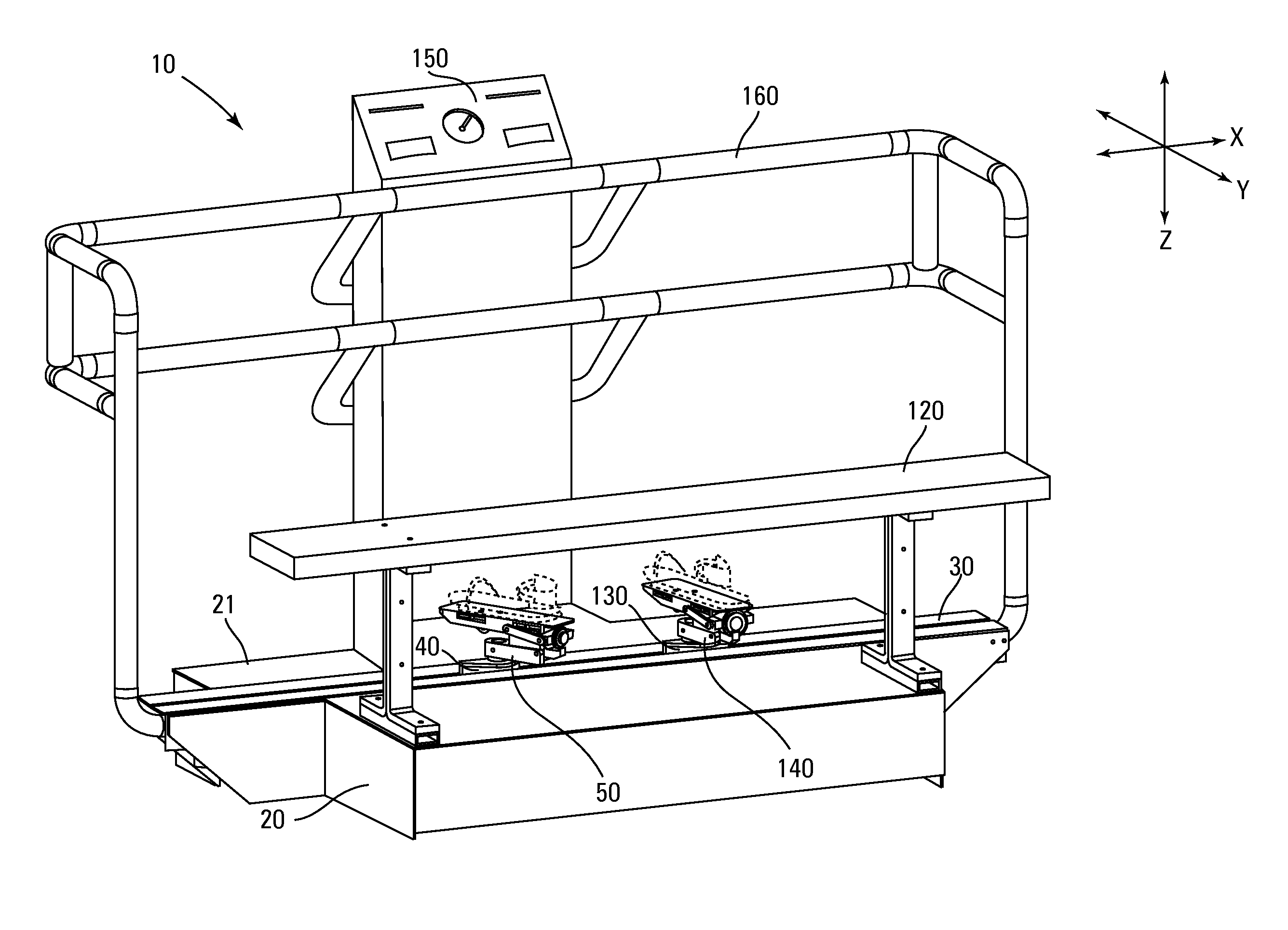
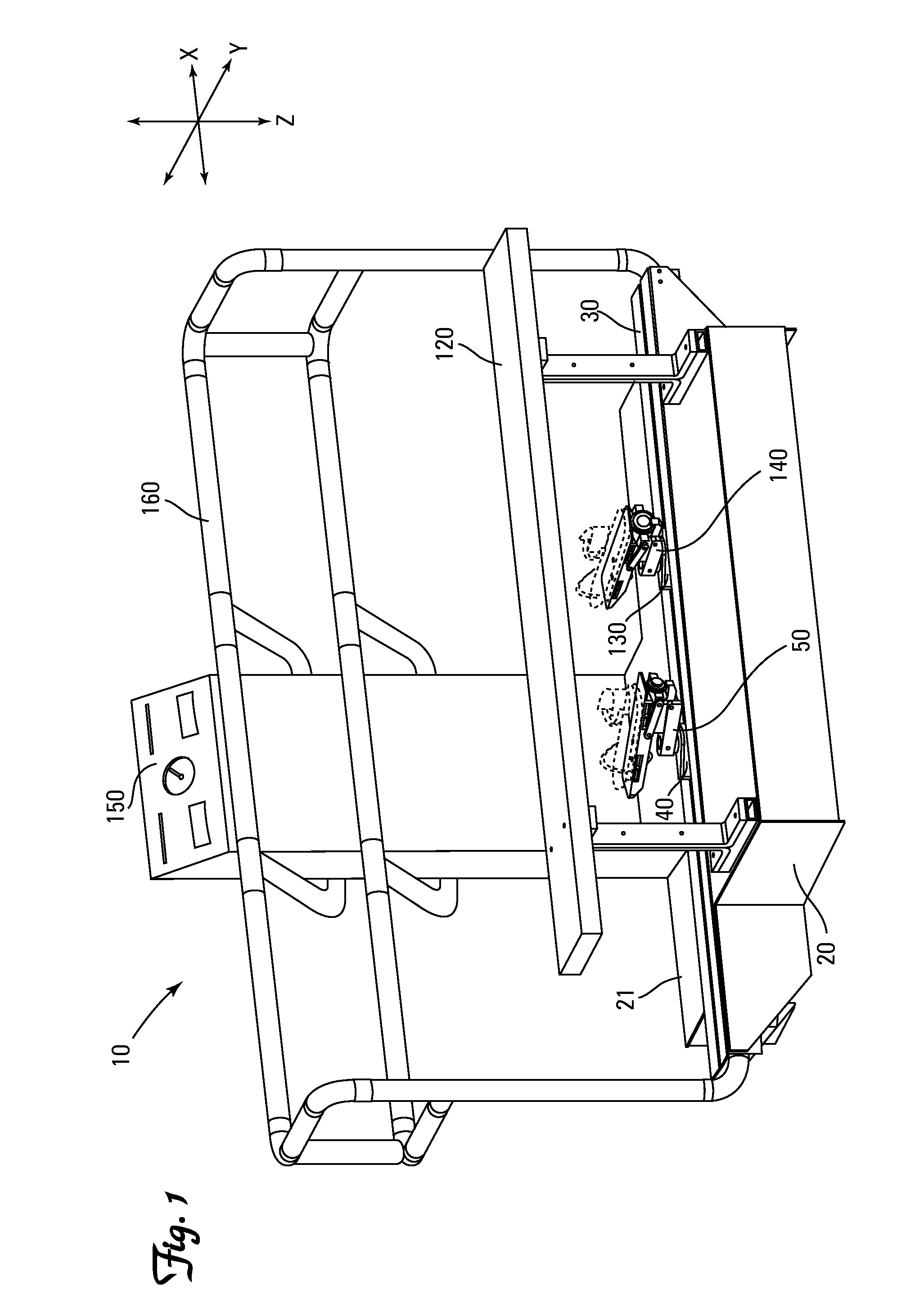
[0144]As shown in FIGS. 7-9, the foot pedal 50 pivotally attaches the foot plate base 52a of the foot pad 52 to an intermediate member 51 for pivoting about a primary lateral axis Y1 and reciprocating in the longitudinal direction X relative to a secondary lateral axis Y2. Preferably the pivot connection (not numbered) is proximate the toe end 56 of the first foot pedal 50. Most preferably the pivot connection is proximate the placement of the ball of the foot on the first foot pedal 50. As shown in FIG. 7, the preferred intermediate member 51 is a piston to allow reciprocating in the longitudinal direction X and rotation about a longitudinal axis X1. A restriction link 54 is pivotally attached to the foot pad 52 proximate the heel end 57 of the foot pad 52 and the intermediate member 51 for pivoting about the secondary lateral axis Y2.

[0145]As shown in FIG. 7, the intermediate member 51 is attached to a base member 53. Preferably the intermediate member 51 is pivotally attached to ...

second embodiment

[0147]As shown in FIG. 17, the foot pedal 250 has a foot pad 252 attached to a longitudinally extending cam 254. The intermediate member 251 is attached to at least one cam roller 255. The cam roller 255 reciprocates in the longitudinal direction X and transverse direction Z along the cam 254. Preferably the cam 254 has a longitudinally extending non-circular arcuate opening 253 through the center (not numbered) of the cam 254. The intermediate member 251 may have a cam roller 255 reciprocating in the longitudinal direction X and transverse direction Z along the non-circular arcuate opening 253 through the center of the cam 254 and one or more additional cam rollers 255 reciprocating in the longitudinal direction X and transverse direction Z along the outer edge (not numbered) of the cam 254.

third embodiment

[0148]As shown in FIG. 18, the foot pedal 350 has a foot pad 352 pivotally attached to a cam roller 355 proximate the toe end 352a of the foot pad 352. A cam 354 is attached to the intermediate member 351. The cam roller 355 reciprocates along an outside edge (not numbered) of a cam 354 in a longitudinal direction X and transverse direction Z. A restriction link 353 is pivotally attached to the foot pad 352 proximate the heel end 352b of the foot pad 352 and pivotally attached to the intermediate member 351 for pivoting about a lateral axis YA.


PUM


Abstract

The invention is a skating simulator 10 having a frame 20, a longitudinally extending rail 30, a carriage 40, and a foot pedal 50. The rail 30 is attached to the frame 20. The carriage 40 operably engages the rail 30 for reciprocating along a path 60 along the rail 30. The foot pedal 50 is attached to the carriage 40. The foot pedal 50 has an intermediate member 51, a foot pad 52, means for attaching the foot pad 52 to the intermediate member 51 allowing non circular arcuate movement of the foot pad 52 in relation to the intermediate member 51 in the longitudinal direction X and transverse direction Z.

Description

[0001]This application claims the benefit of U.S. Provisional Application No. 61 / 091,810, filed Aug. 26, 2008.BACKGROUND[0002]A skating simulator is a machine or device designed to assist an individual in simulating, in whole or in part, the act of skating. Previous attempts to re-create the skating motion have met with mixed results.[0003]Over the years different inventors have approached the task of building a good skating simulator from a few different directions. Of the numerous patent filings in the area of machines intended to simulate skating or skiing they all fall into one of three or four basic categories. One such type is a Lateral Linear Motion Machine (LLMM). A LLMM is a machine designed to facilitate lateral travel across its surface. The individual using the LLMM abducts and adducts one or both hips while sliding laterally with one or both feet.[0004]LLMMs can be divided into two categories as well. A Full Lateral Linear Motion Machine (FLLMM) is a machine that will a...

Claims


Application Information

Patent Timeline
Patent Type & Authority Applications(United States)
IPC IPC(8): A63B22/00
CPCA63B21/157A63B21/225A63B22/0046A63B22/201A63B21/1492A63B69/0057A63B2022/003A63B21/1488A63B69/0022A63B21/4045A63B21/4047
Inventor HALVER, TERRENCE
Owner HALVER TERRENCE
Why Eureka
Try Eureka