Drillstring motion analysis and control

a technology of drillstring and motion analysis, applied in the direction of survey, instrument, borehole/well accessories, etc., can solve the problems of reducing drilling efficiency, reducing drilling efficiency, and causing chaos

Inactive Publication Date: 2011-06-23
HALLIBURTON ENERGY SERVICES INC
View PDF17 Cites 43 Cited by
  • Summary
  • Abstract
  • Description
  • Claims
  • Application Information

AI Technical Summary

Problems solved by technology

A number of undesirable conditions can develop while drilling a borehole.
This can quickly become a chaotic phenomenon in which the drillstring seems to randomly bounce back and forth,

Method used


Image

  • Drillstring motion analysis and control
  • Drillstring motion analysis and control
  • Drillstring motion analysis and control

Examples


Embodiment Construction

[0007]Time series measurements made using accelerometers and other motion-sensitive sensors can be used to diagnose undesirable vibration phenomena that occur as part of drilling operations. Because of inter-related effects, a reliable diagnosis can be difficult to make when several phenomena exist simultaneously. However, if enough motion-sensitive sensors are used, along with instrumentation for real-time standoff measurements, the various modes of drillstring motion can be isolated by combining the sensor outputs. Unfortunately, due to constraints on funding and computer resources, this type of operation is not practical.

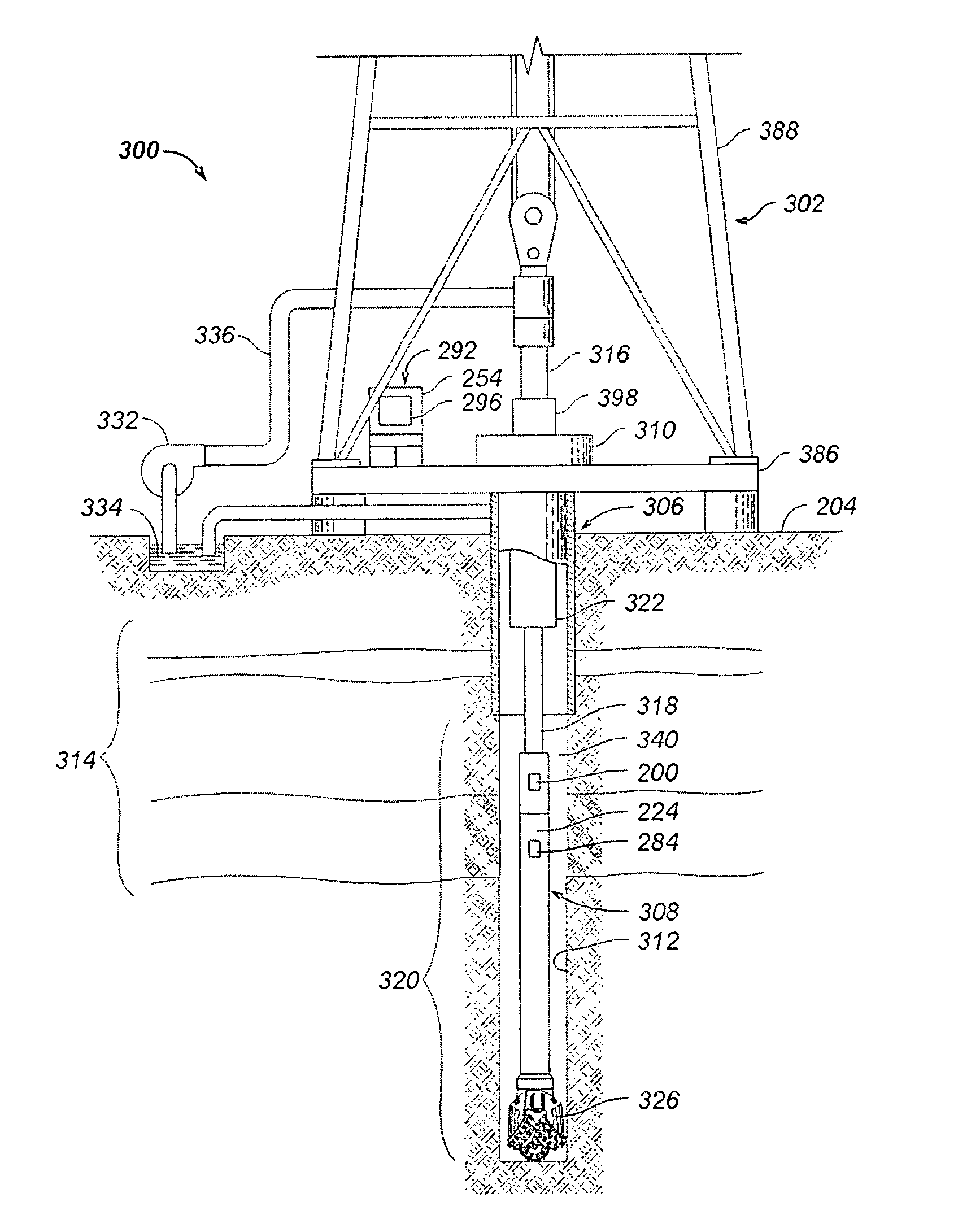
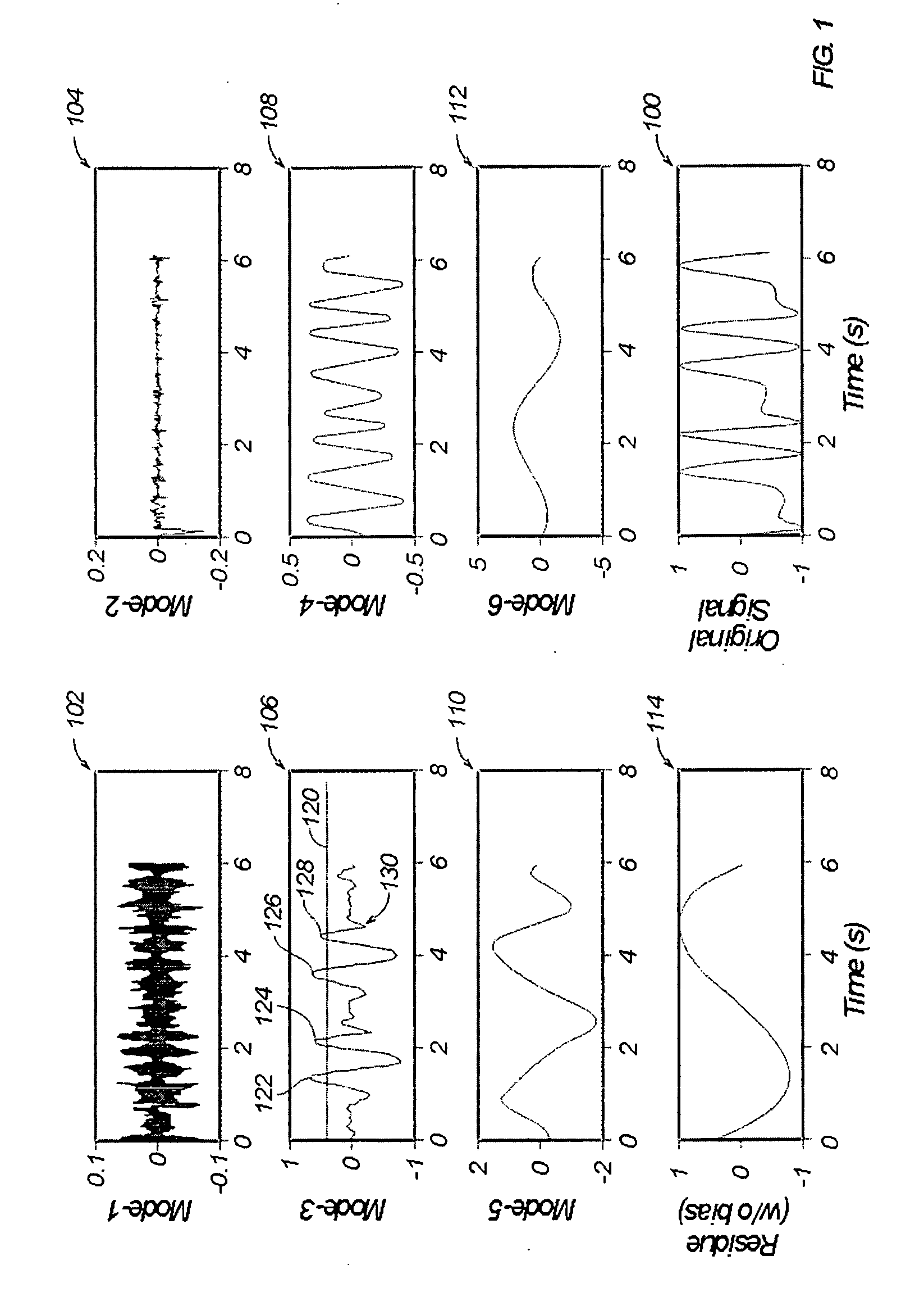
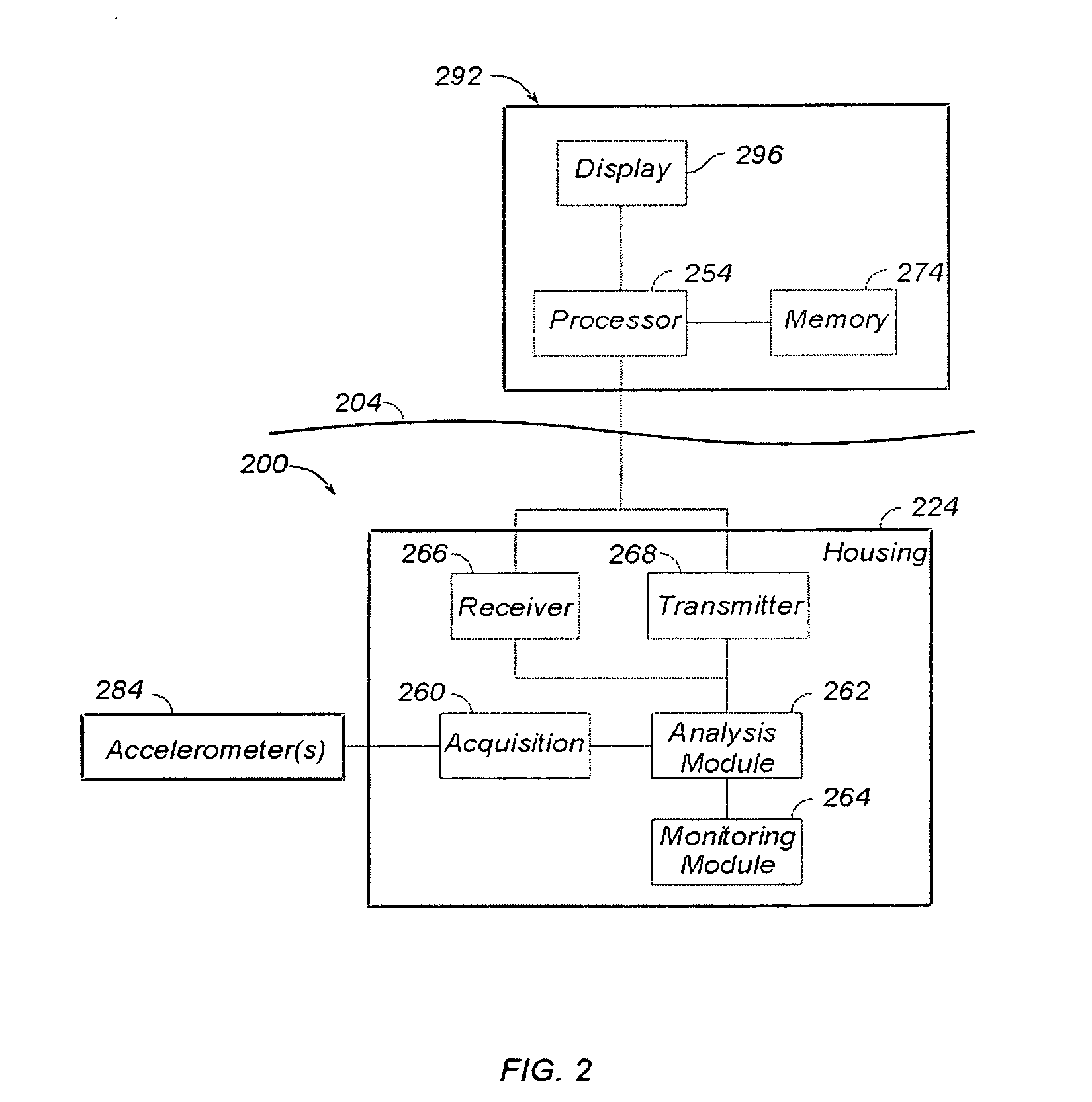
[0008]As an alternative, a mechanism is disclosed herein that permits identifying various modes of vibrational motion presented by a bottom hole assembly (BHA) using a single measurement vehicle (e.g., a single accelerometer). By deriving modal decomposition information from surface or downhole (or both) acceleration sensors, and identifying / correlating the behav...


PUM


Abstract

Apparatus, systems, and methods may operate to obtain acceleration data from an operational drillstring, decompose the acceleration data into one or more empirical modes, monitor the amplitude of at least one of the empirical modes to detect indications exceeding a preselected threshold, and modify drillstring operational parameters comprising at least one of rotational speed, weight on bit, or mud flow, based on the indications. Additional apparatus, systems, and methods are disclosed.

Description

BACKGROUND INFORMATION[0001]A number of undesirable conditions can develop while drilling a borehole. For example, standing vibration waves can be generated along the drillstring, leading to a condition known as stick / slip. In this condition, the drillstring stops rotating for a period of time, and then spins free. The resulting instantaneous rotation frequency can be high enough to loosen the coupling between drillstring elements. Another condition is known as whirl, in which the bit, or a portion of the drillstring, rotates around the circumference of the borehole (instead of substantially centered within the borehole). This can quickly become a chaotic phenomenon in which the drillstring seems to randomly bounce back and forth, slapping against the sides of the borehole. These conditions, and others, can result in reduced drilling efficiency, and may even cause the drillstring to become stuck in the borehole.BRIEF DESCRIPTION OF THE DRAWINGS[0002]FIG. 1 illustrates accelerometer ...

Claims


Application Information

Patent Timeline
IPC IPC(8): E21B47/16
CPCE21B44/00E21B47/0006E21B47/00E21B47/007
Inventor RODNEY, PAUL F.
Owner HALLIBURTON ENERGY SERVICES INC
Why Eureka
Try Eureka