

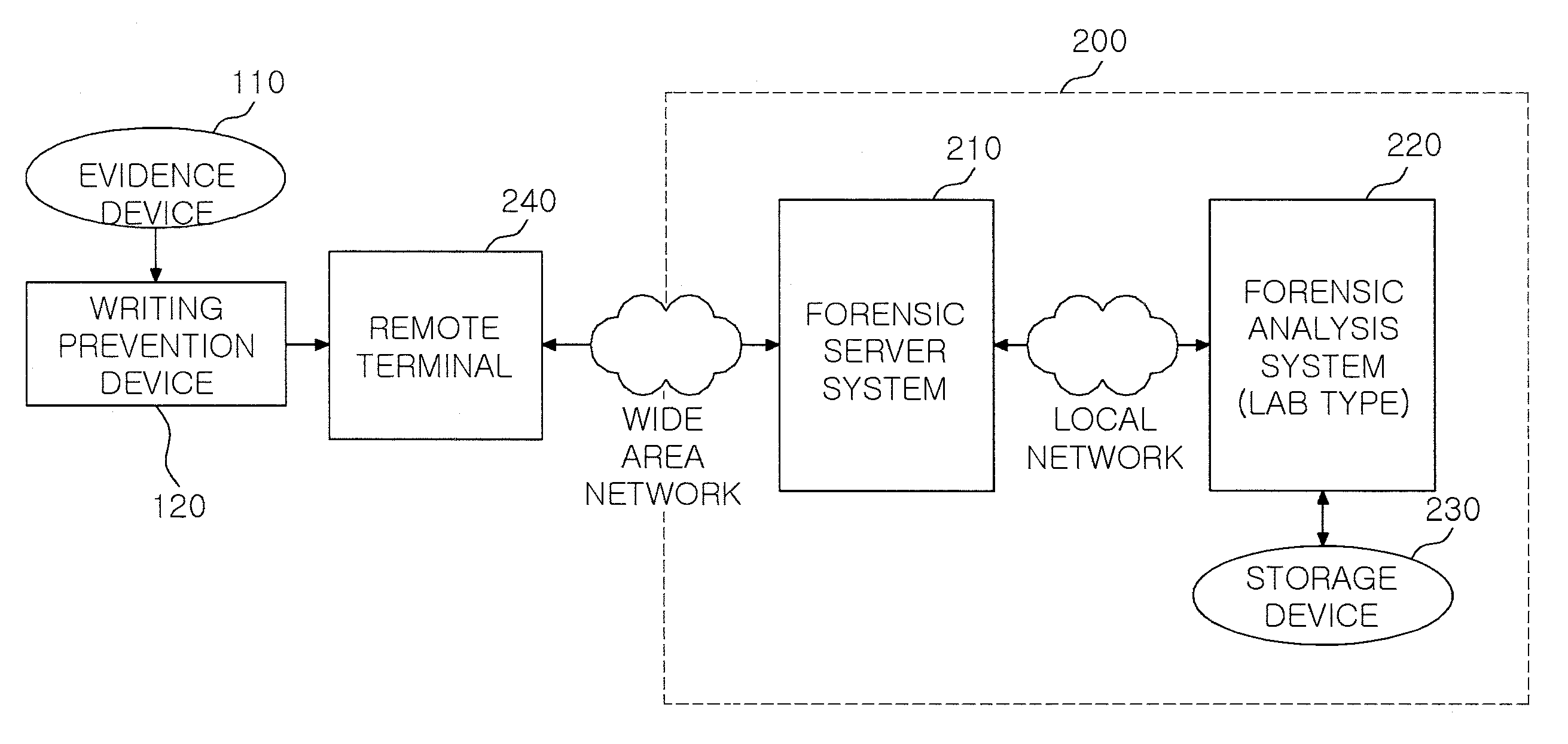
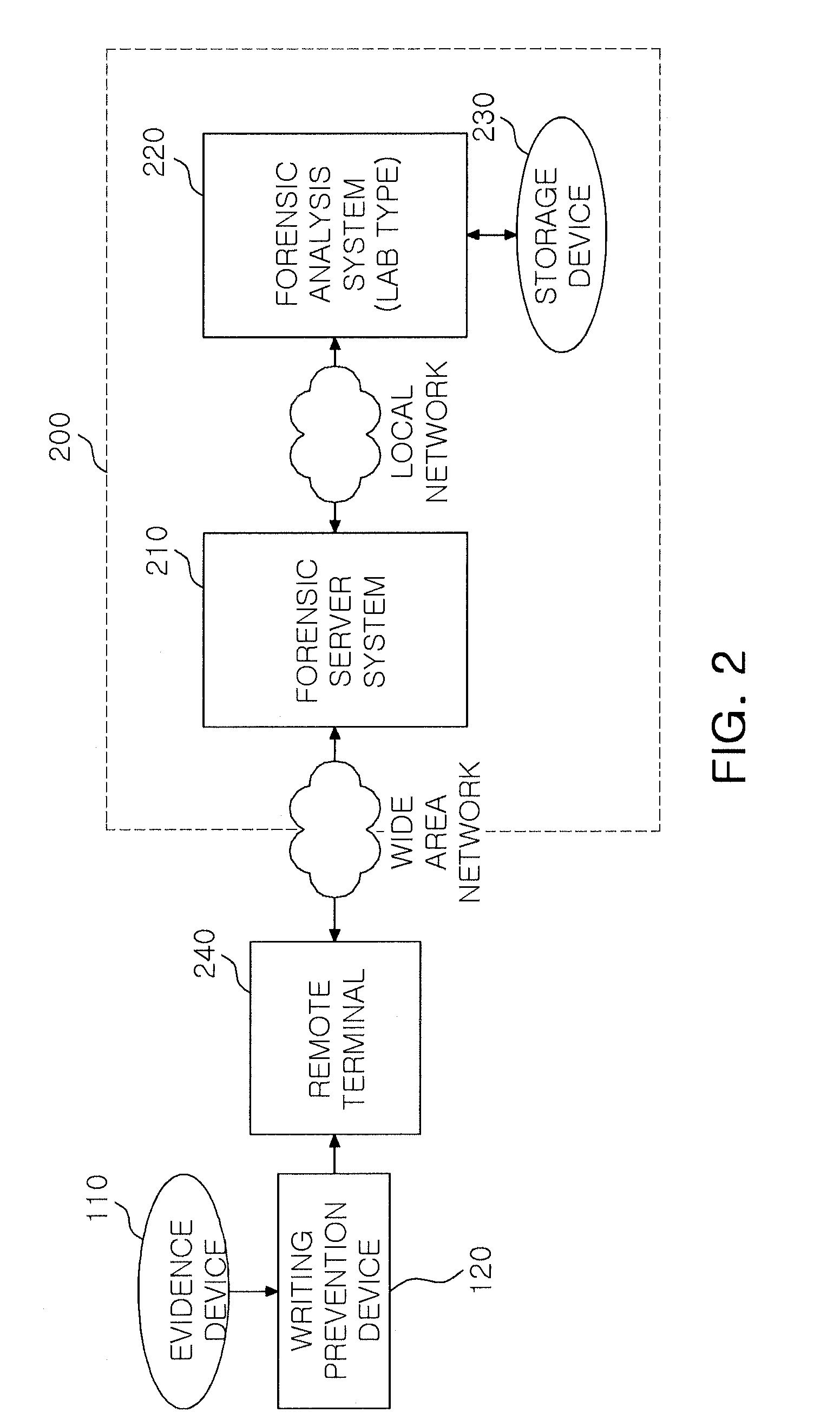
Remote forensics system based on network
a remote forensics and network technology, applied in the field of remote forensics systems based on networks, can solve the problems of large amount of temporal and monetary costs, unfit analysis of large capacity data, anti-forensic technique-applied data, etc., and achieve the effect of increasing processing capacity and speed
- Summary
- Abstract
- Description
- Claims
- Application Information
AI Technical Summary
Benefits of technology
Problems solved by technology
Method used
Image

Examples
Embodiment Construction
[0055]The present invention may be modified variably and may have various embodiments, particular examples of which will be illustrated in drawings and described in detail.
[0056]However, it should be understood that the following exemplifying description of the invention is not intended to restrict the invention to specific forms of the present invention but rather the present invention is meant to cover all modifications, similarities and alternatives which are included in the spirit and scope of the present invention.
[0057]While terms such as “first” and “second,” etc., may be used to describe various components, such components must not be understood as being limited to the above terms. The above terms are used only to distinguish one component from another. For example, a first component may be referred to as a second component without departing from the scope of rights of the present invention, and likewise a second component may be referred to as a first component. The term “a...
PUM
 Abstract
Description
Claims
Application Information