Frequency-tunable bracketless fluid manifold

a bracketless, fluid manifold technology, applied in mechanical equipment, machines/engines, manufacturing tools, etc., can solve the problems of high engineering cost, significant vibration of manifolds during engine operation, and relatively high system weigh

Active Publication Date: 2011-06-30
GENERAL ELECTRIC CO
View PDF20 Cites 10 Cited by
  • Summary
  • Abstract
  • Description
  • Claims
  • Application Information

AI Technical Summary

Problems solved by technology

Such manifolds experience significant vibration during engine operation.
This requires a substantial design effort and testing iterati

Method used


Image

  • Frequency-tunable bracketless fluid manifold
  • Frequency-tunable bracketless fluid manifold
  • Frequency-tunable bracketless fluid manifold

Examples


Embodiment Construction

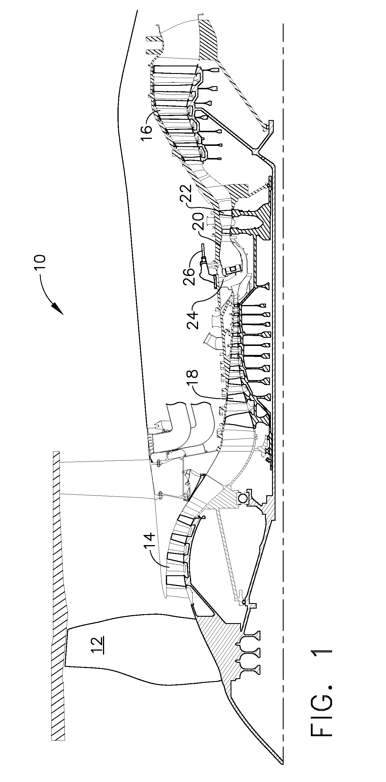
[0020]Referring to the drawings wherein identical reference numerals denote the same elements throughout the various views, FIG. 1 depicts an exemplary gas turbine engine 10 having a fan 12, a low pressure compressor or “booster”14 and a low pressure turbine (“LPT”) 16 collectively referred to as a “low pressure system”, and a high pressure compressor (“HPC”) 18, a combustor 20, and a high pressure turbine (“HPT”) 22, collectively referred to as a “gas generator” or “core”. Together, the high and low pressure systems are operable in a known manner to generate a primary or core flow as well as a fan flow or bypass flow. While the illustrated engine 10 is a high-bypass turbofan engine, the principles described herein are equally applicable to turboprop, turbojet, and turboshaft engines, as well as turbine engines used for other vehicles or in stationary applications. The principles of this invention are also equally applicable to other fields where a vibration-resistant fluid manifold...


PUM

PropertyMeasurementUnit
Shapeaaaaaaaaaa
Radiusaaaaaaaaaa

Abstract

A fluid manifold apparatus includes: (a) an array of spaced-apart manifold fittings, each manifold fitting aligned in a predetermined angular orientation. Each manifold fitting includes: (i) a tubular neck; (ii) a pair of spaced-apart tubular arms extending away from a first end of the neck; and (iii) a coupling connected to a second end of the neck; and (b) a plurality of curved tubes, each tube being coupled to one arm of each of two adjacent manifold fittings.

Description

BACKGROUND OF THE INVENTION[0001]This invention relates generally to fluid handling, and more particularly to apparatus and methods for fluid manifolds in gas turbine engines.[0002]A gas turbine engine includes a turbomachinery core having a high pressure compressor, a combustor, and a high pressure turbine in serial flow relationship. The core is operable in a known manner to generate a primary gas flow. Depending on the engine's configuration, the core may be combined with a fan and low pressure turbine system to generate propulsive thrust, or with a work turbine to extract mechanical energy and turn a driveshaft or propeller.[0003]In conventional gas turbine engines, fuel is introduced to the combustor through an array of fuel nozzles which are coupled to an external manifold surrounding the combustor. In operation, pressurized fuel is fed to the manifold. The manifold then distributes the pressurized fuel to the individual fuel nozzles. Such manifolds are commonly manufactured f...

Claims


Application Information

Patent Timeline
IPC IPC(8): F02C7/22
CPCF01N13/18Y10T29/49826F02C7/222Y10T29/49398F05D2250/71F05D2260/96F05D2230/51F05D2250/75F05D2220/32
Inventor FIEBIG, KEVIN MICHAELBROWN, JOSHUANATH, JOSEPH
Owner GENERAL ELECTRIC CO
Why Eureka
Try Eureka