Plasma reactor and etching method using the same

a plasma reactor and etching technology, applied in the field of plasma reactors, can solve the problems of difficult to freely change the plasma density in the course of the etching process, the difficulty of a very thin photoresist pattern to sufficiently protect the region of a workpiece not to etch from plasma, and the complex etching process using the multi-stack structure etch mask

Active Publication Date: 2011-06-30
DMS CO LTD
View PDF5 Cites 6 Cited by
  • Summary
  • Abstract
  • Description
  • Claims
  • Application Information

AI Technical Summary

Benefits of technology

[0009]An aspect of exemplary embodiments of the present invention is to address at least the problems and / or disadvantages and to provide at least the advantages described below. Accordingly, an aspect of exemplary embodiments of the present invention is to provide an etching method using a plasma reactor, for selectively switching ON or OFF a plurality of switches connected between a plurality of inductive coils and a Radio Frequency (RF) source power generator according to a set etching condition and selectively changing a combination structure of the plurality of inductive coils, thereby being capable of securing a process uniformity and continuously executing etching processes of different conditions.

Problems solved by technology

This makes it very difficult for a very thin photoresist pattern to sufficiently protect a region of a workpiece not to etch from plasma in the etching process for obtaining a pattern of a high aspect ratio (i.e., a pattern of a large H / W ratio (H: Height of workpiece pattern obtained from etching and W: Width of workpiece pattern obtained from etching)).
Compared to the etching process carried out with only the photoresist pattern laminated on the workpiece, an etching process using the multi-stack structure etch mask is much more complex.
However, the conventional plasma reactor is difficult to freely change the plasma density in course of the etching process.
Also, due to the phenomenon in which the ERs of the center part and edge part of the workpiece are given differently from each other, it is very difficult to secure process uniformity when etching the workpiece having the multi-stack structure etch mask laminated thereon.
That is, it is difficult to secure the uniform ER in the center part and edge part of the large workpiece.

Method used


Image

  • Plasma reactor and etching method using the same
  • Plasma reactor and etching method using the same
  • Plasma reactor and etching method using the same

Examples


Embodiment Construction

[0028]Exemplary embodiments of the present invention will now be described in detail with reference to the annexed drawings. In the following description, a detailed description of known functions and configurations incorporated herein has been omitted for conciseness.

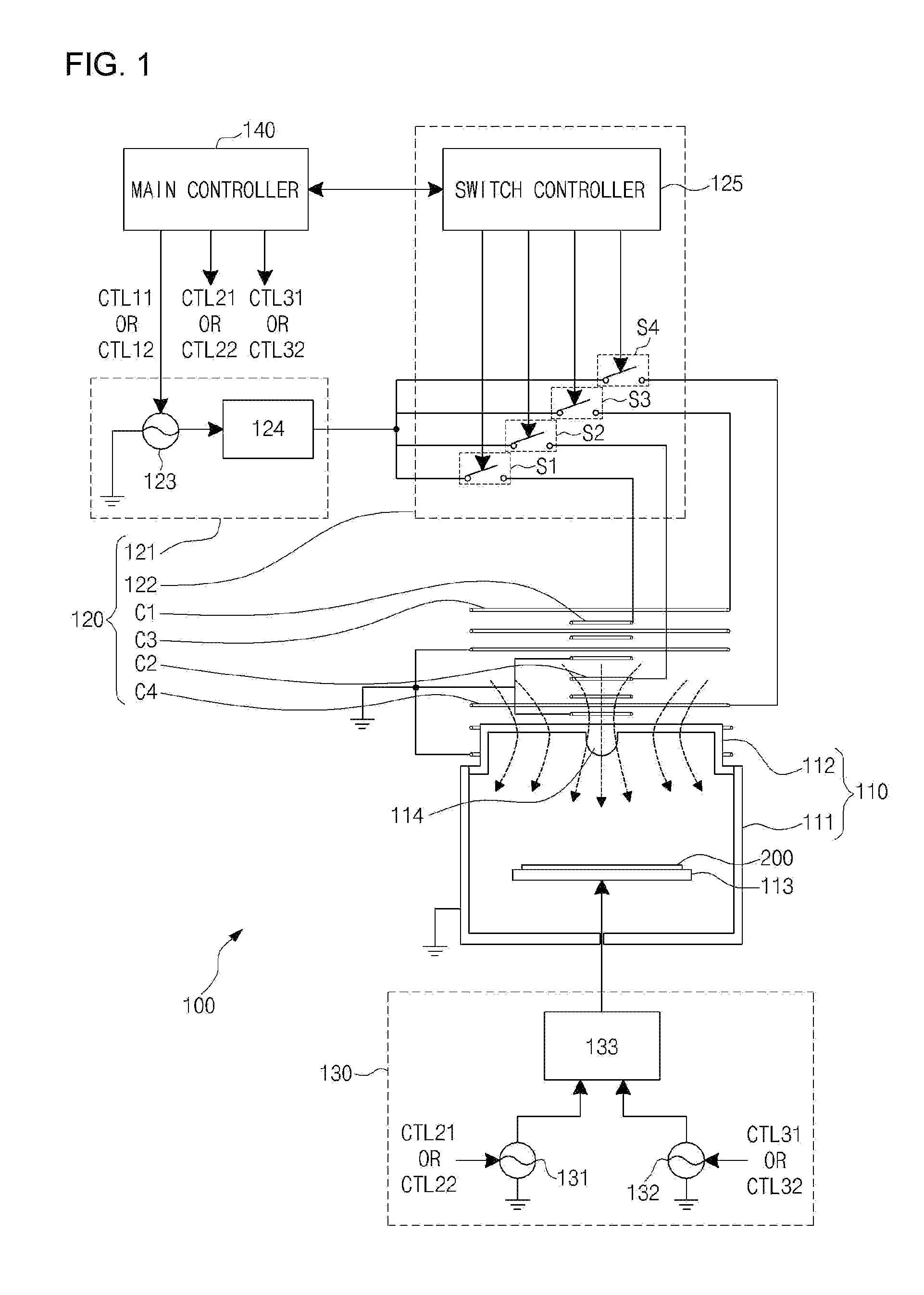
[0029]FIG. 1 is a schematic diagram illustrating a plasma reactor according to an exemplary embodiment of the present invention. For the simplicity of the drawings, FIG. 1 illustrates only parts related to the present invention. The plasma reactor 100 includes a reaction chamber 110, an Inductive Coupled Plasma (ICP) source power unit 120, and a Radio Frequency (RF) bias power supply unit 130.

[0030]The reaction chamber 110 includes a body 111 and a dielectric window 112. A cathode assembly 113 is installed within the body 111. The body 111 is opened at its top. The body 111 connects to the ground. The dielectric window 112 can be formed in a cylinder shape. The dielectric window 112 is installed to seal the opened top ...


PUM

PropertyMeasurementUnit
thicknessaaaaaaaaaa
diameteraaaaaaaaaa
pressureaaaaaaaaaa

Abstract

A plasma reactor and an etching method using the same are provided. The method includes a first changing step of changing the number or arrangement structure of inductive coils connecting to an RF source power supply unit, a step of applying RF source power and generating high density plasma, a first etching step of etching a first etch-target layer of a workpiece, a first stopping step of stopping applying the RF source power, a second changing step of changing the number or arrangement structure of the inductive coils, a step of applying RF source power to corresponding inductive coils and generating low density plasma, a second etching step of etching a second etch-target layer of the workpiece, and a second stopping step of stopping applying the RF source power.

Description

CROSS REFERENCE[0001]This application claims foreign priority under Paris Convention and 35 U.S.C. §119 to Korean Patent Application No. 10-2009-0130381, filed Dec. 24, 2009 with the Korean Intellectual Property Office.BACKGROUND OF THE INVENTION[0002]1. Field of the Invention[0003]The present invention relates to a plasma reactor used in a semiconductor fabrication process. More particularly, the present invention relates to an Inductive Coupled Plasma (ICP) type plasma reactor and an etching method using the same.[0004]2. Description of the Related Art[0005]In recent years, as a Critical Dimension (CD) of a workpiece pattern obtained from etching is reduced to 50 nm or less in an etching process of a plasma reactor, a thickness of a photoresist layer used as an etch mask of a workpiece gets thinner. This makes it very difficult for a very thin photoresist pattern to sufficiently protect a region of a workpiece not to etch from plasma in the etching process for obtaining a pattern ...

Claims


Application Information

Patent Timeline
Patent Type & Authority Applications(United States)
IPC IPC(8): H01L21/3065
CPCH01J37/321H01L21/31116H01J37/32266H01L21/3065
Inventor JANG, HYEOKJINKIM, MINSHIKLEE, KWANGMINKO, SUNGYONGCHAE, HWANKOOKPARK, KUNJOOKIM, KEEHYUNLEE, WEONMOOK
Owner DMS CO LTD
Why Eureka
Try Eureka