Showerhead, substrate processing apparatus including the showerhead, and plasma supplying method using the showerhead

a showerhead and substrate technology, applied in the field of showerheads, can solve the problems of space filling, uniform thickness over a wafer, and quality of deposited films, and achieve the effect of ensuring process uniformity

Inactive Publication Date: 2010-08-05
EUGENE TECH CO LTD
View PDF9 Cites 21 Cited by
  • Summary
  • Abstract
  • Description
  • Claims
  • Application Information

AI Technical Summary

Benefits of technology

[0018]According to the present invention, it is possible to control the supply of plasma, thereby securing process uniformity.

Problems solved by technology

One of the important issues is quality of the deposited films.
Another important issue is uniform thickness over a wafer.
Another issue related to the deposition is space filling, which includes gap filling to fill gaps defined between metal lines with an insulation film including an oxide film.
Among the above-described issues, the uniformity is one of the important issues related to the deposition process.
A nonuniform film causes high electrical resistance on the metal lines, which increases a possibility of mechanical breakage.

Method used


Image

  • Showerhead, substrate processing apparatus including the showerhead, and plasma supplying method using the showerhead
  • Showerhead, substrate processing apparatus including the showerhead, and plasma supplying method using the showerhead
  • Showerhead, substrate processing apparatus including the showerhead, and plasma supplying method using the showerhead

Examples


first embodiment

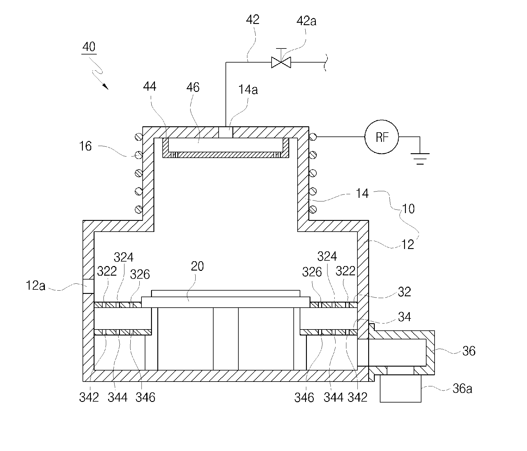
[0030]FIG. 1 is a view schematically illustrating a substrate processing apparatus according to the present invention.

[0031]The substrate processing apparatus includes a chamber 10 defining an inner space where a process is carried out with respect to a substrate. The chamber 10 includes a process chamber 12 and a generation chamber 14. In the process chamber 12, a process is carried out with respect to the substrate. In the generation chamber 14, plasma is generated from a source gas supplied from a gas supply unit 40, which will be described hereinafter.

[0032]In the process chamber 12 is installed a support plate 20. The substrate is placed on the support plate 20. The substrate is introduced into the process chamber 12 through an inlet port 12a formed at one side of the process chamber 12. The introduced substrate is placed on the support plate 20. The support plate 20 may be an electrostatic chuck (E-chuck). Also, a helium (He) rear cooling system (not shown) may be provided to ...

second embodiment

[0046]FIG. 6 is a view schematically illustrating a substrate processing apparatus according to the present invention. As shown in FIG. 6, the substrate processing apparatus further includes a guide tube 50.

[0047]The guide tube 50 has a cross sectional shape generally corresponding to the shape of the substrate. For example, when the substrate is rectangular, the guide tube 50 has a rectangular shape in cross section. When the substrate is circular, the guide tube 50 has a circular shape in cross section. The guide tube 50 extends from the top wall of the process chamber 12 and the lower end of the generation chamber 14 toward the support plate 20. The lower end of the guide tube 50 is spaced a predetermined distance from the support plate 20. Consequently, it is possible for plasma to be introduced into the exhaust line 36 through a gap defined between the lower end of the guide tube 50 and the support plate 20.

[0048]As shown in FIG. 6, plasma generated in the generation chamber 14...

third embodiment

[0049]FIG. 7 is a view schematically illustrating a substrate processing apparatus according to the present invention. The substrate processing apparatus further includes a showerhead 60 and a support frame 70. The showerhead 60 is disposed above the support plate 20 such that the showerhead 60 is spaced a predetermined distance from the support plate 20. The showerhead 60 is placed at the upper end of the support frame 70. The lower end of the support frame 70 is connected to the top of the first exhaust plate 32. The support frame 70 supports the showerhead 60 and, at the same time, protects the support plate 20 and a heater (not shown) mounted in the support plate 20.

[0050]FIGS. 8 to 10 are views illustrating the showerhead 60 of FIG. 6. The showerhead 60 includes a central plate 62, a boundary plate 66, and connection bars 68 inter-connecting the central plate 62 and the boundary plate 66. The showerhead 60 supplies plasma generated in the generation chamber 14 to the substrate ...


PUM

PropertyMeasurementUnit
electric fieldaaaaaaaaaa
areaaaaaaaaaaa
compositionaaaaaaaaaa

Abstract

A showerhead includes a first ring having an inner spray port formed therein, a second ring configured to surround the first ring, the second ring being disposed outside the first ring such that the second ring is spaced apart from the first ring, and a connection member for interconnecting the first ring and the second ring. An outer spray port is formed between the first ring and the second ring. The showerhead further includes a third ring disposed in the inner spray port formed in the first ring and a fourth ring disposed in the outer spray port formed between the first ring and the second ring. The third ring has an innermost spray port formed therein, and the fourth ring has an outermost spray port formed at the outside thereof.

Description

TECHNICAL FIELD [0001]The present invention relates to a showerhead, a substrate processing apparatus including the showerhead, and a plasma supplying method using the showerhead, and, more particularly, to a showerhead having a first ring and a second ring, a substrate processing apparatus including the showerhead, and a plasma supplying method using the showerhead.BACKGROUND ART[0002]A semiconductor device has a plurality of layers on a silicon substrate. The layers are deposited on the substrate through a deposition process. The deposition process has several important issues, which are important in evaluating deposited films and selecting a deposition method.[0003]One of the important issues is quality of the deposited films. The quality includes composition, contamination level, defect density, and mechanical and electrical properties. The composition of films may change depending upon deposition conditions, which is very important in obtaining a specific composition.[0004]Anot...

Claims


Application Information

Patent Timeline
Patent Type & Authority Applications(United States)
IPC IPC(8): C23C16/455C23C16/00
CPCH01J37/32357H01J37/32422H01J37/3244H01J2237/3323H01J37/32623H01J37/32834H01J37/32449
Inventor YOON, SONG KEUNSONG, BYOUNG GYULEE, JAE HOKIM, KYONG HUN
Owner EUGENE TECH CO LTD
Why Eureka
Try Eureka