

Passive infrared detector
a detector and infrared technology, applied in the direction of optical radiation measurement, instruments, sensing radiation from moving bodies, etc., can solve the problems of nuisance alarms, detectors may sense unintended targets, innocent passersby, nuisance alarms,
- Summary
- Abstract
- Description
- Claims
- Application Information
AI Technical Summary
Problems solved by technology
Method used
Image

Examples
Embodiment Construction
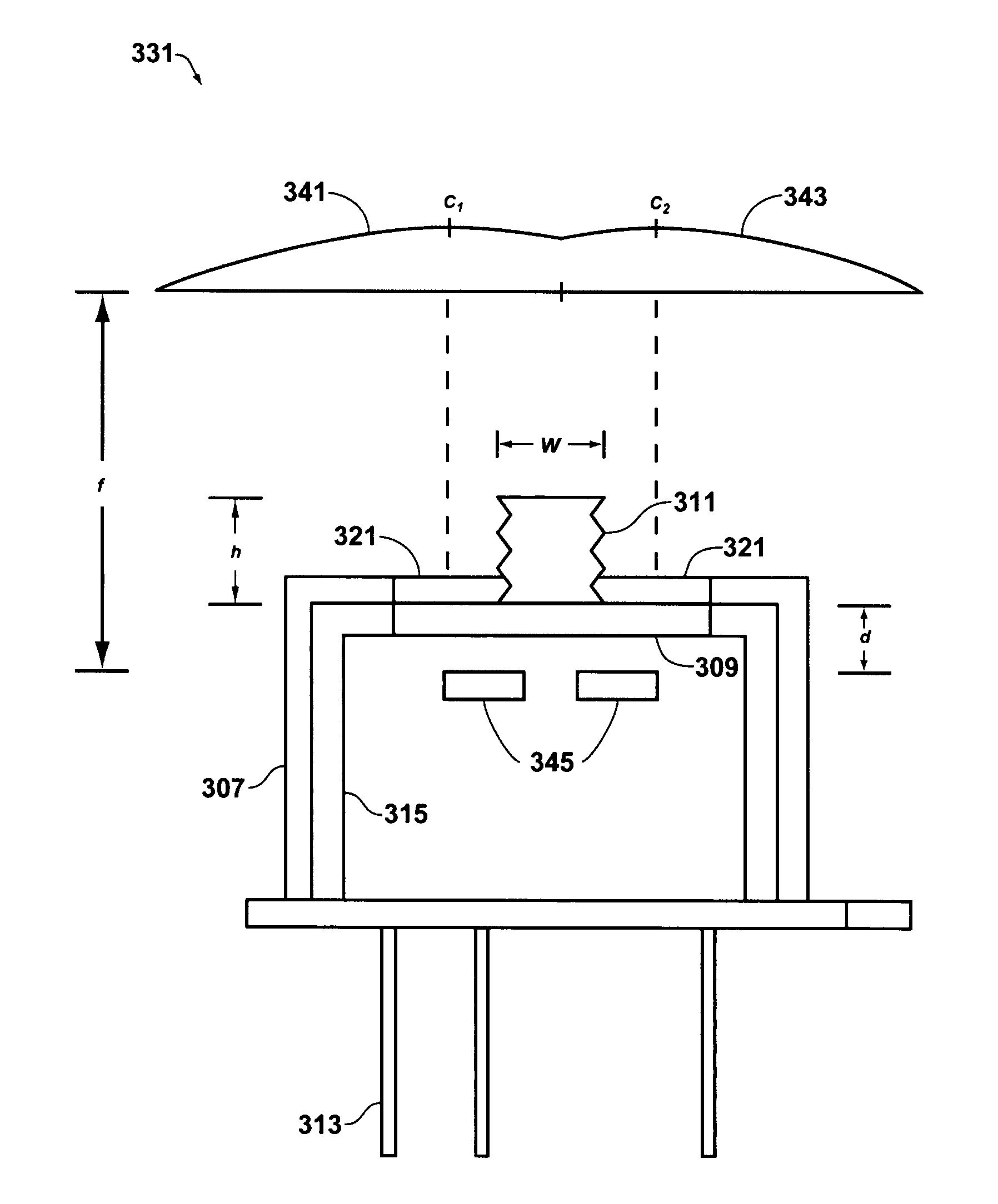
[0028]As used herein, the term “aperture stop” refers to an element (in an infrared detector of the type described herein) which is placed in the optical path of a detector to modify the ray cone angle at an image point. This element may be, for example, a diaphragm or septum, or the edge of a lens or mirror.
[0029]In one aspect, an infrared detector is provided which comprises a pyroelectric detector having first and second sensing elements, an aperture stop, and a Fresnel lens array.
[0030]In another aspect, an infrared detector is provided which comprises a window; first and second sensing elements disposed on a first side of a window; an aperture stop disposed on a second side of a window; and a Fresnel lens array; wherein the Fresnel lens array has a finite focal length.
[0031]It has now been found that the aforementioned needs in the art may be met through the provision of an infrared motion detector which is equipped with a pyroelectric detector having an aperture stop disposed ...
PUM
 Abstract
Description
Claims
Application Information