Image capturing apparatus and control method thereof

a technology control method, which is applied in the field of vibration correction of image capturing apparatus, can solve the problems of affecting the quality of captured images, the general poorness of angular velocity detection characteristic at low frequencies, and the known vibration correction method using both optical and electronic vibration correction systems, etc., to achieve the effect of improving the ability to correct for vibration

Inactive Publication Date: 2011-06-30
CANON KK
View PDF4 Cites 32 Cited by
  • Summary
  • Abstract
  • Description
  • Claims
  • Application Information

AI Technical Summary

Benefits of technology

[0007]The present invention has been made in consideration of the above situation, and improves the vibration correction ability while ameliorating vibrations during the accumulation period of time in a vibration correction method using both optical and electronic vibration correction systems.

Problems solved by technology

Recently, as image capturing apparatuses become more compact and the magnification produced by optical systems become higher, vibration of the image capturing apparatus can greatly degrade the quality of a captured image.
However, the known correction method using both optical and electronic vibration correction systems suffers the following problems.
However, the angular velocity detection characteristic generally becomes poor at low frequencies, of 1 Hz or less.
Furthermore, the electronic vibration correction system cannot correct vibrations during the accumulation period of time.
When all remaining vibrations, which cannot be corrected for by the optical vibration correction system, are subjected to correction by the electronic vibration correction system based on detection of a blur between images, the image quality deteriorates owing to vibrations during the accumulation period of time due to the generation of large amplitude low frequency vibrations.

Method used


Image

  • Image capturing apparatus and control method thereof
  • Image capturing apparatus and control method thereof
  • Image capturing apparatus and control method thereof

Examples


first embodiment

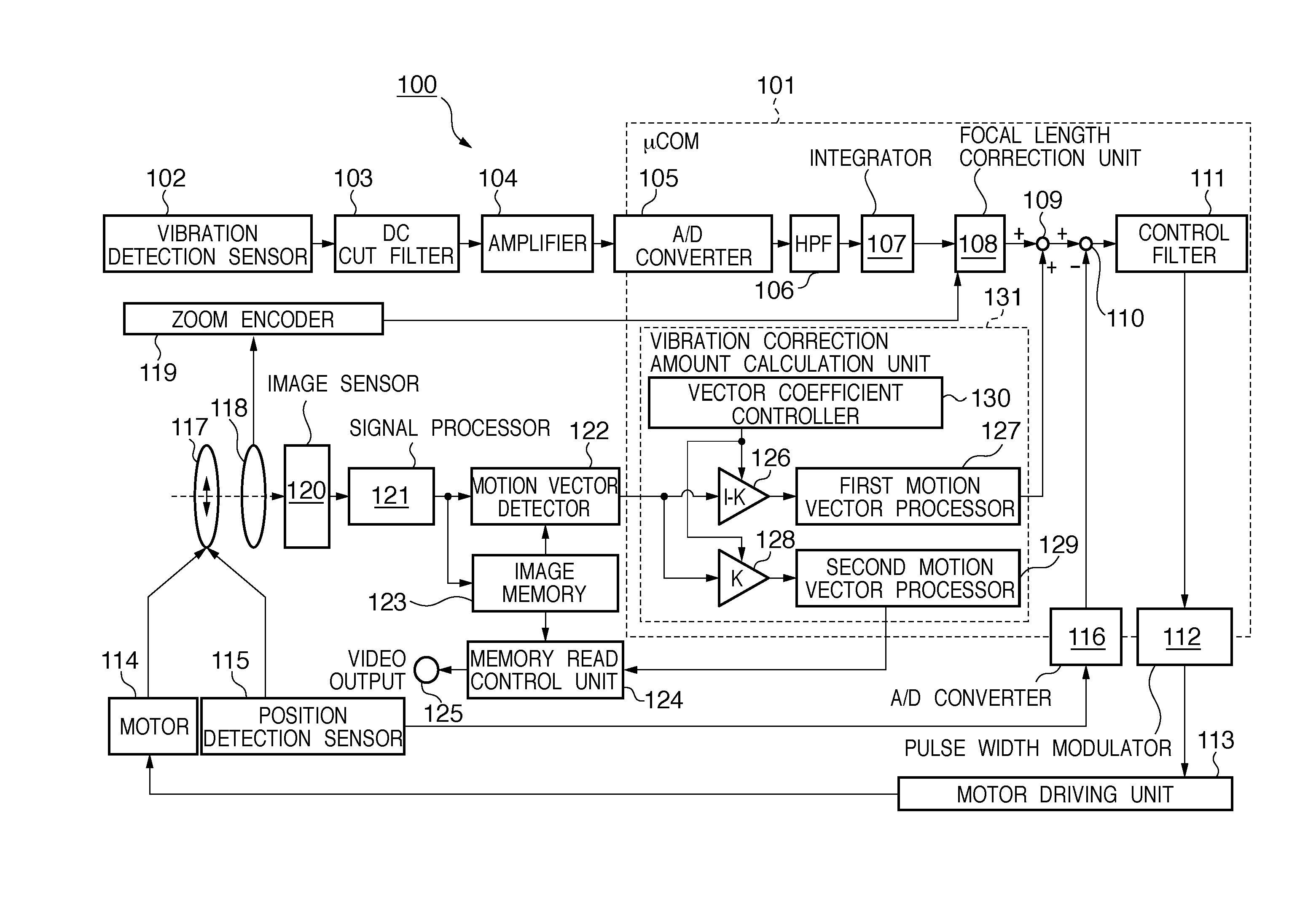
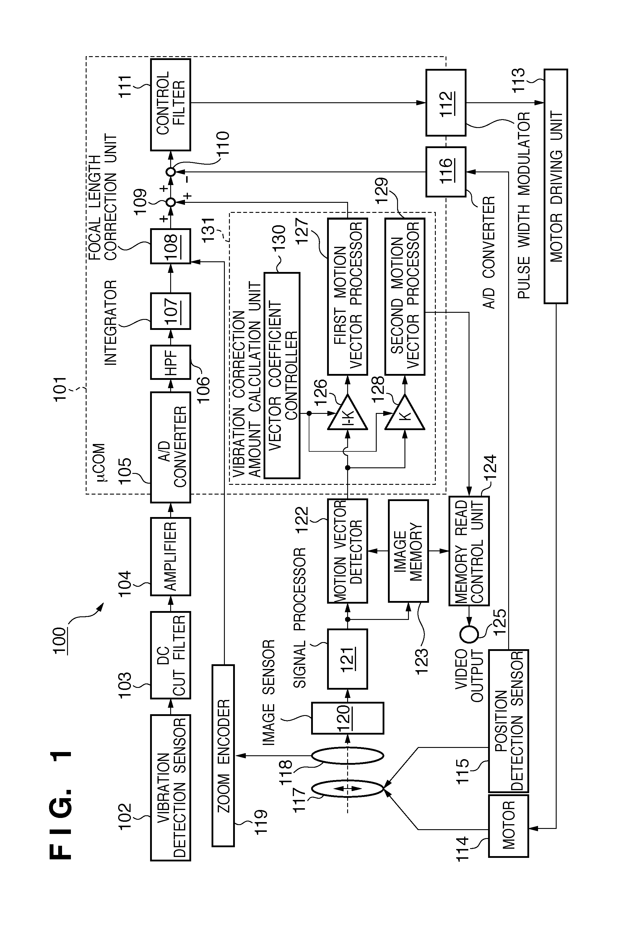
[0029]The processing of determining the coefficient K by a vector coefficient controller 130 in an image capturing apparatus 100 having the above arrangement according to the first embodiment of the present invention will be explained.

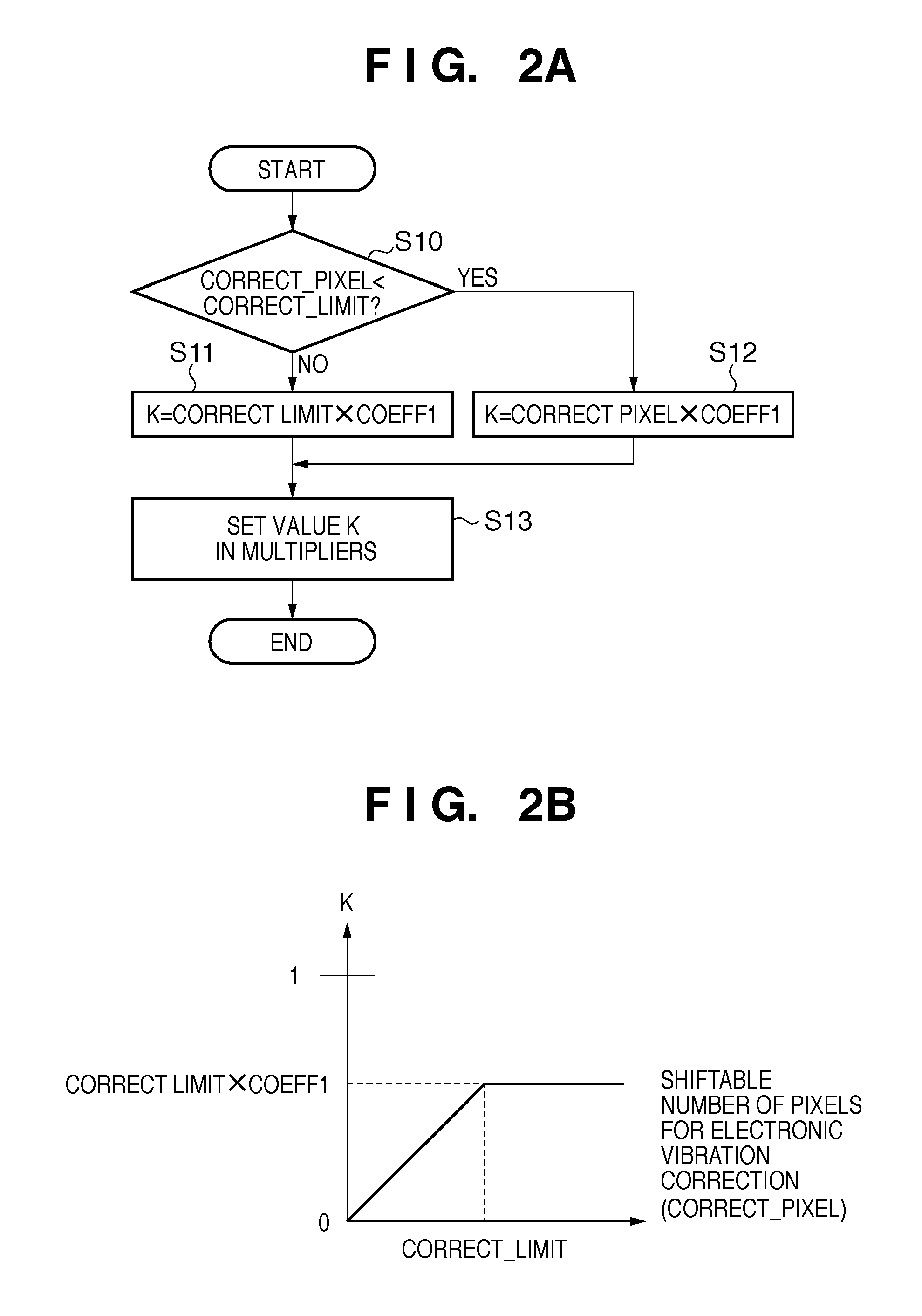
[0030]FIG. 2A is a flowchart exemplifying processing by the vector coefficient controller 130. This processing is repeatedly performed in every predetermined period such as 1 / 60 sec.

[0031]In step S10, the vector coefficient controller 130 determines whether the shiftable number of pixels (CORRECT_PIXEL) for electronic vibration correction is smaller than a predetermined value CORRECT_LIMIT. In electronic vibration correction, a partial area (for example, area B in FIG. 3) is extracted from the entire image sensing area (for example, area A in FIG. 3) read out from an image sensor 120, and the position of the read area is changed within the image sensing area so as to cancel vibrations. For example, in FIG. 3, the shiftable number of pixels for electron...

second embodiment

[0041]Processing of determining the coefficient K by a vector coefficient controller 130 according to the second embodiment of the present invention will be explained.

[0042]FIG. 4A is a flowchart exemplifying processing by the vector coefficient controller 130. This processing is repetitively performed in every predetermined period such as 1 / 60 sec.

[0043]In step S20, the vector coefficient controller 130 determines, as the value (0≦K≦1) of the coefficient K, a value obtained by adding a predetermined value K_MAX_WIDE to a value obtained by multiplying the focal length f of the image capturing apparatus by a predetermined coefficient COEFF2:

coefficient K=focal length f of image capturing apparatus×predetermined coefficient COEFF2+predetermined value K_MAX_WIDE

for −K_MAX_WIDE / F_TELE≦COEFF2<0

−F_TELE×COEFF2K_MAX_WIDE−F_WIDE×COEFF2

where F_TELE is the focal length at the telephoto end, and F_WIDE is the focal length at the wide-angle end. The focal length f is calculated from current zoom...

third embodiment

[0047]Processing of determining the coefficient K by a vector coefficient controller 130 according to the third embodiment of the present invention will be explained.

[0048]FIG. 5A is a flowchart exemplifying processing by the vector coefficient controller 130. This processing is repetitively performed in every predetermined period such as 1 / 60 sec.

[0049]In step S30, the vector coefficient controller 130 determines, as the value of the coefficient K, a value obtained by adding a predetermined value K_MAX_HIGH_SPEED to a value obtained by multiplying the shutter speed SS of the image capturing apparatus by a predetermined coefficient COEFF3:

coefficient K=shutter speed SS×predetermined coefficient COEFF3+predetermined value K_MAX_HIGH_SPEED

[0050]Letting SLOW_SS be the slowest shutter speed of the image capturing apparatus, relations:

−K_MAX_HIGH_SPEED / SLOW_SS

−SLOW_SS×COEFF3<K_MAX_HIGH_SPEED<1−HIGH_SS×COEFF3

hold. In step S31, the vector coefficient controller 130 sets the det...


PUM


Abstract

An image capturing apparatus comprises: an image sensing unit arranged to sense an object image; a vibration detection unit arranged to detect a vibration applied to the image capturing apparatus; a vector detection unit arranged to detect a motion vector from an image sensed by the image sensing unit; a first calculation unit arranged to calculate a first correction amount from a signal obtained based on an output from the vibration detection unit and a signal based on the motion vector; a second calculation unit arranged to calculate a second correction amount based on the motion vector; a first correction unit arranged to optically correct the vibration based on the first correction amount; and a second correction unit arranged to correct the vibration by changing an image read region based on the second correction amount, wherein vibration correction is performed using both the first and second correction units.

Description

BACKGROUND OF THE INVENTION[0001]1. Field of the Invention[0002]The present invention relates to a technique of correcting for vibrations of an image capturing apparatus using both optical and electronic vibration correction systems in the image capturing apparatus.[0003]2. Description of the Related Art[0004]Recently, as image capturing apparatuses become more compact and the magnification produced by optical systems become higher, vibration of the image capturing apparatus can greatly degrade the quality of a captured image. Various vibration correction functions have been proposed, which correct the blur of a captured image, arising from vibration of the imaging apparatus. A conventional vibration correction function mounted in an image capturing apparatus is known in which the correction method uses both optical and electronic vibration correction systems (see, for example, Japanese Patent No. 2803072).[0005]Firstly, the optical vibration correction system detects vibrations of ...

Claims


Application Information

Patent Timeline
Patent Type & Authority Applications(United States)
IPC IPC(8): H04N5/232
CPCG02B27/646G03B5/02G03B2217/005H04N5/23248G03B2205/0007H04N23/68
Inventor MIYASAKO, KENICHI
Owner CANON KK
Why Eureka
Try Eureka