Liquid crystal display panel and liquid crystal display device using the same

a liquid crystal display panel and liquid crystal display technology, applied in non-linear optics, instruments, optics, etc., can solve the problems of inconsistent brightness of liquid crystal display panels and deterioration of display quality, so as to reduce the occurrence of streaks, shorten the time for resuming the stable state, and increase the brightness

Active Publication Date: 2011-06-30
INNOLUX CORP
View PDF4 Cites 8 Cited by
  • Summary
  • Abstract
  • Description
  • Claims
  • Application Information

AI Technical Summary

Benefits of technology

[0008]The invention is directed to a liquid crystal display panel and a liquid crystal display device using the same, which reduce the occurrence of streaks, increase the brightness and shorten the time for resuming the stable state so as to improve the display quality and product competitiveness.

Problems solved by technology

Or, the brightness of the liquid crystal display panel may become inconsistent during the display of frames so as to deteriorate the display quality.

Method used


Image

  • Liquid crystal display panel and liquid crystal display device using the same
  • Liquid crystal display panel and liquid crystal display device using the same
  • Liquid crystal display panel and liquid crystal display device using the same

Examples


first embodiment

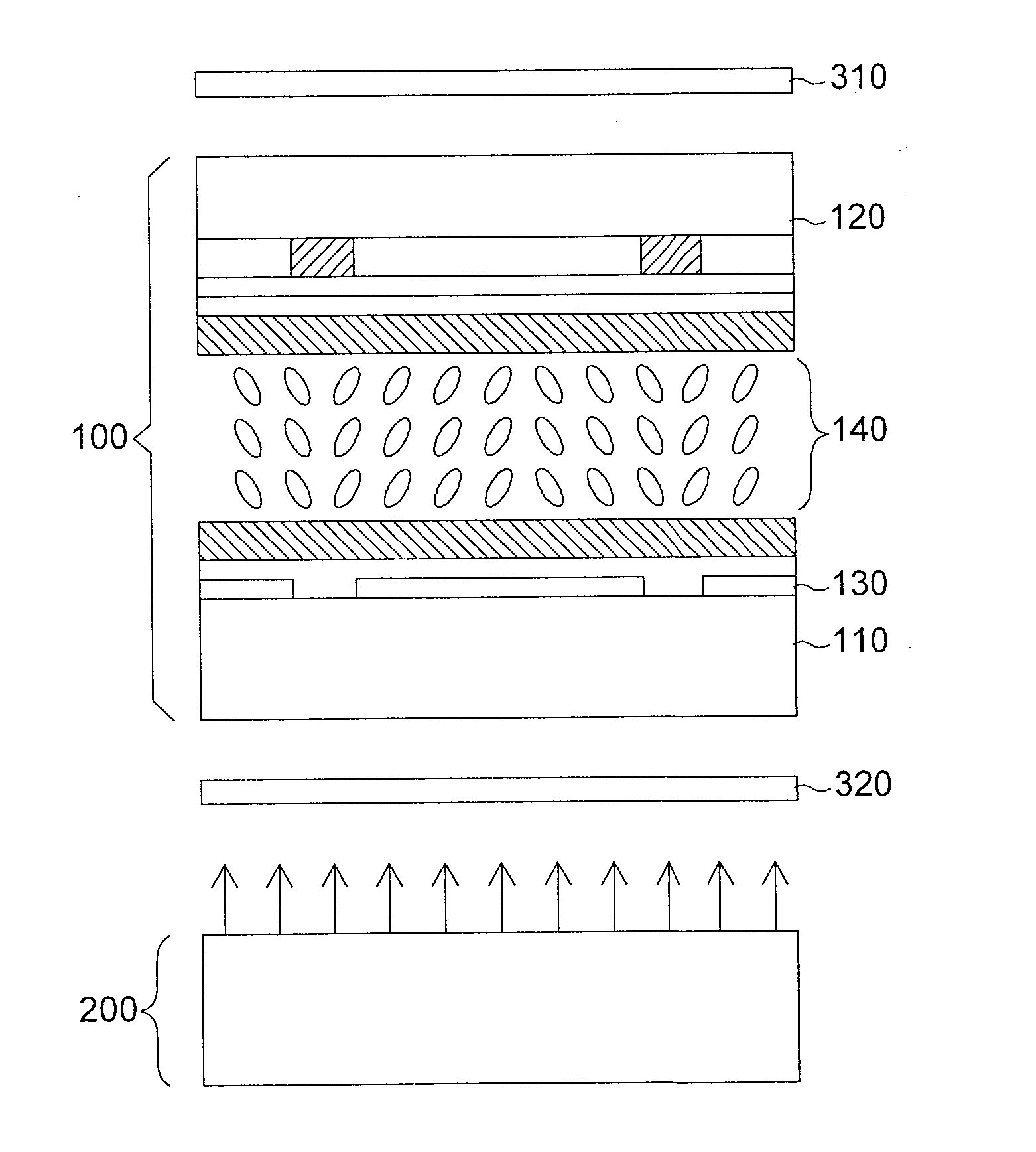
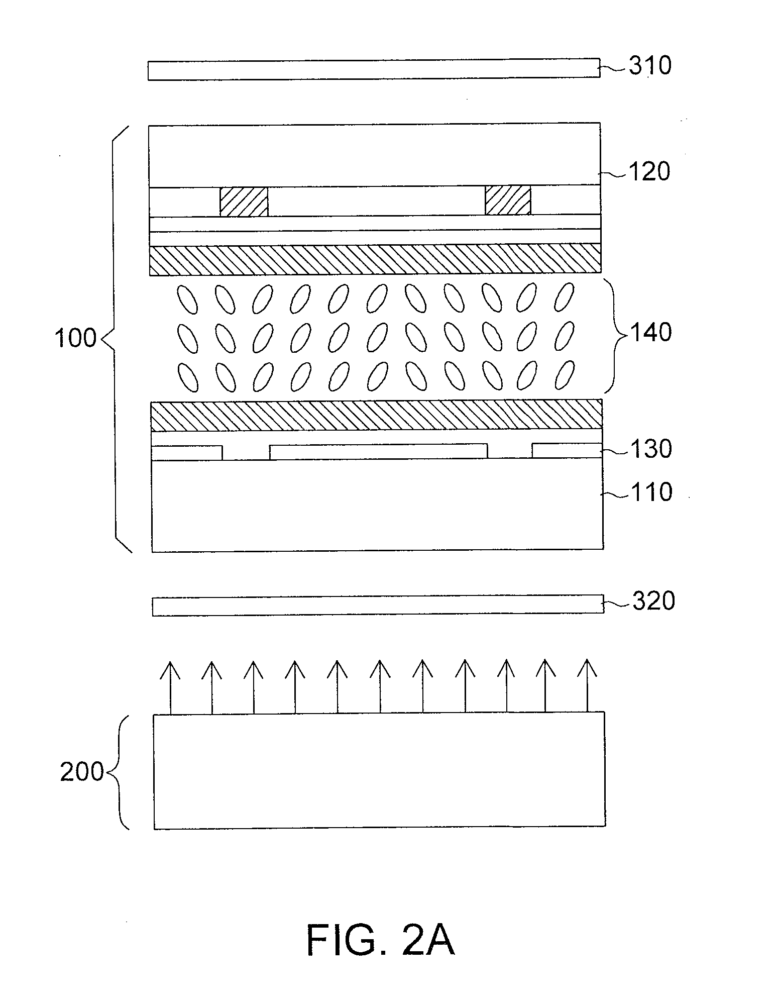
[0021]Referring to FIG. 2A, a liquid crystal display device according to a first embodiment of the invention is shown. The liquid crystal display device includes a liquid crystal display panel 100, a backlight module 200 and polarizers 310 and 320. The absorption axes of the polarizers 310 and 320 are perpendicular to each other. The liquid crystal display panel 100 is disposed between the polarizers 310 and 320. The backlight module 200 is used for providing light for the liquid crystal display panel 100 to display an image.

[0022]The liquid crystal display panel 100 includes a first substrate 110, a second substrate 120, an electrode structure 130 and a liquid crystal layer 140. The second substrate 120 is substantially parallel to the first substrate 110. The liquid crystal layer 140 is located between the first substrate 110 and the second substrate 120. The electrode structure 130 is disposed on the first substrate 110.

[0023]Referring to FIG. 2B, an electrode structure 130 in FI...

second embodiment

[0028]Referring to FIG. 3, an electrode structure 230 according to a second embodiment of the invention is shown. A first branch portion 231b of an electrode structure 230 includes several first branch electrodes 231b1. The two adjacent first branch electrodes 231b1 are substantially parallel to each other and separated apart by a first interval d21. A second branch portion 232b of the electrode structure 230 includes several second branch electrodes 232b1. The two adjacent second branch electrodes 232b1 are substantially parallel to each other and separated apart by a second interval d22. In the present embodiment of the invention, any of the second branch electrodes 232b1 corresponds to at least part of one of the first intervals d21, and any of the first branch electrodes 231b1 corresponds to at least part of one of the second intervals d22, so the advantages of the liquid crystal display panel equipped with the electrode structure 230 are similar to that of the liquid crystal di...

third embodiment

[0031]Referring to FIG. 4, an electrode structure 330 according to a third embodiment of the invention is shown. The electrode structure 330 includes a sub-electrode structure S31 including a first stem electrode 331t and a first branch portion 331b, and a sub-electrode structure S32 including a second stem electrode 332t and a second branch portion 332b. The sub-electrode structures S31 and S32 are vertically adjacent to each other.

[0032]Since any of second branch electrodes 332b1 of the second branch portion 332b corresponds to at least part of one first interval d31, and any of first branch electrodes 331b1 of the first branch portion 331b corresponds to at least part of one second interval d32, the liquid crystal display panel equipped with the electrode structure 330 has similar advantages like the liquid crystal display panel 100 of the first embodiment.


PUM

PropertyMeasurementUnit
unit length U1aaaaaaaaaa
timeaaaaaaaaaa

Abstract

A liquid crystal display panel includes a first substrate, a second substrate, a liquid crystal layer and an electrode structure. The second substrate is substantially parallel to the first substrate. The liquid crystal layer is located between the first substrate and the second substrate. The electrode structure is disposed on the first substrate. The electrode structure includes a first branch portion and a second branch portion. The first branch portion includes first branch electrodes. The two adjacent first branch electrodes are substantially parallel to each other and separated apart by a first interval. The second branch portion includes second branch electrodes. The two adjacent second branch electrodes are substantially parallel to each other and separated apart by a second interval. Any first branch electrode corresponds to at least part of one of the second intervals. Any second branch electrode corresponds to at least part of one of the first intervals.

Description

[0001]This application claims the benefit of Taiwan application Serial No. 98145117, filed Dec. 25, 2009, the subject matter of which is incorporated herein by reference.BACKGROUND OF THE INVENTION[0002]1. Field of the Invention[0003]The invention relates in general to a liquid crystal display panel and a liquid crystal display device using the same, and more particularly to a multi-domain liquid crystal display panel and a liquid crystal display device using the same.[0004]2. Description of the Related Art[0005]In recent years, display technology has gained significant progress, and the market demand for liquid crystal display is booming. The display quality of a liquid crystal display is essential in the display industry. Currently, wide angle technology has gradually become an important factor in the quality assessment of the liquid crystal display. In the wide angle technology, multi-domain vertical alignment (MVA) technology attracts more and more interest.[0006]In general, the...

Claims


Application Information

Patent Timeline
Patent Type & Authority Applications(United States)
IPC IPC(8): G02F1/1343
CPCG02F1/133707G02F2001/134345G02F1/134336G02F1/134309G02F1/134345
Inventor CHEN, CHIEN HONGYANG, CHING CHE
Owner INNOLUX CORP
Why Eureka
Try Eureka