Power input stabilizing circuit

a power input and stabilizing circuit technology, applied in the direction of power conversion systems, emergency protective arrangements for limiting excess voltage/current, electrical appliances, etc., can solve the problems of heat dissipation and power supply, compromising the durability of highly compact and delicate electronic components, and still susceptible to spikes or current impulses, so as to achieve the effect of suppressing impulse current and enhancing performance and durability of electrical or electronic appliances using the power input stabilizing circui

Inactive Publication Date: 2011-06-30
WU HUI MING +1
View PDF5 Cites 7 Cited by
  • Summary
  • Abstract
  • Description
  • Claims
  • Application Information

AI Technical Summary

Benefits of technology

[0004]To sustain the spikes and current impulses resulted from power on / off or induced by thunder lighting, the present invention provides a first resistor at the input terminals to suppress impulse current. Then, the power passes through a power input limiting circuit including a non-polarity capacitor, a rectifier circuit formed by diodes, and a polarity capacitor so as to provide a current within a specific range to a load. A constant current circuit is then employed to stabilize the load current. As described, the present invention suppresses impulse current and stabilizes the load current through the power input limiting circuit and the constant current circuit. The performance and durability of the electrical or electronic appliance using the power input stabilizing circuit are therefore enhanced significantly.

Problems solved by technology

As electrical and electronic appliances are continuously driven to be even more compact and highly efficient, heat dissipation and power supply have become major design issues to the durability of these appliances.
However, it is still susceptible to spikes or current impulses when the appliance is turned on or off.
These impulses usually would mistakenly trigger electronic components and compromise the durability of the highly compact and delicate electronic components.

Method used


Image

  • Power input stabilizing circuit
  • Power input stabilizing circuit
  • Power input stabilizing circuit

Examples


Embodiment Construction

[0010]The following descriptions are exemplary embodiments only, and are not intended to limit the scope, applicability or configuration of the invention in any way. Rather, the following description provides a convenient illustration for implementing exemplary embodiments of the invention. Various changes to the described embodiments may be made in the function and arrangement of the elements described without departing from the scope of the invention as set forth in the appended claims.

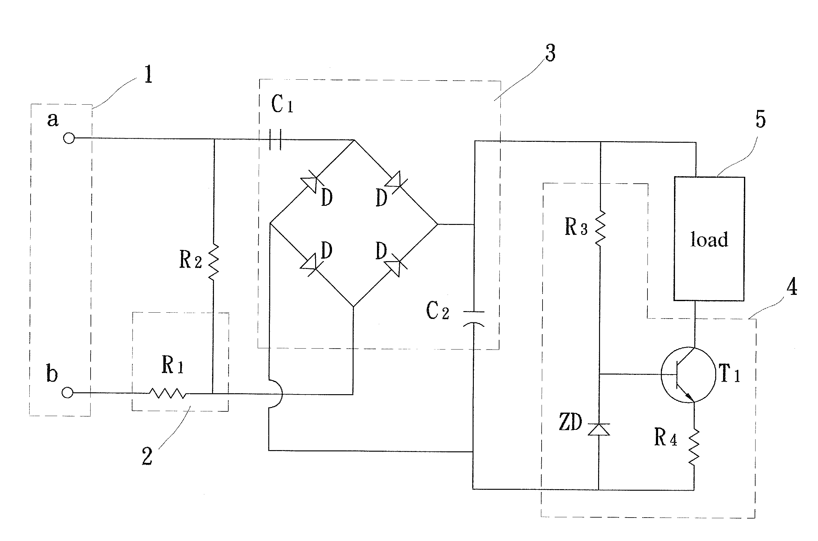
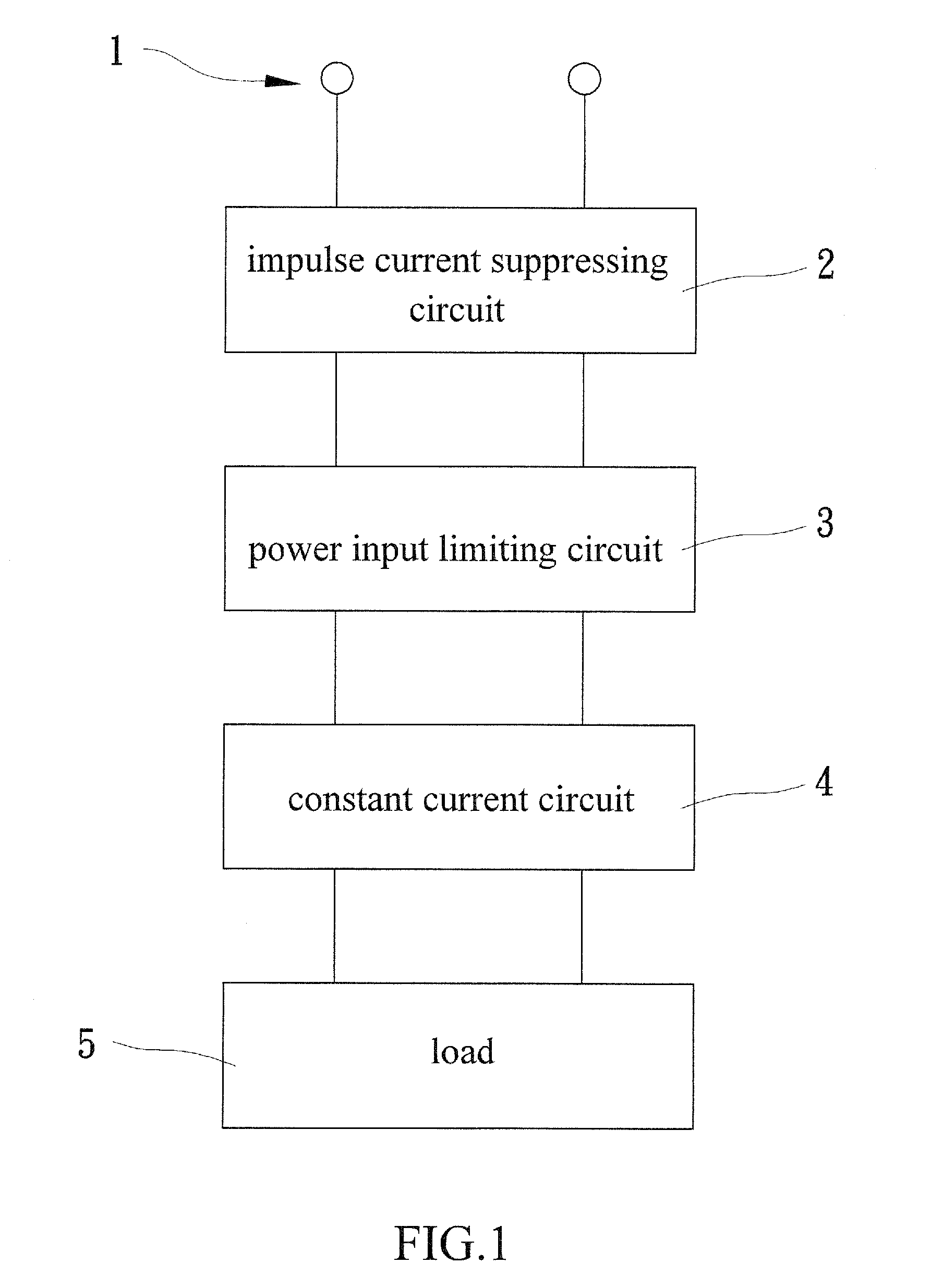
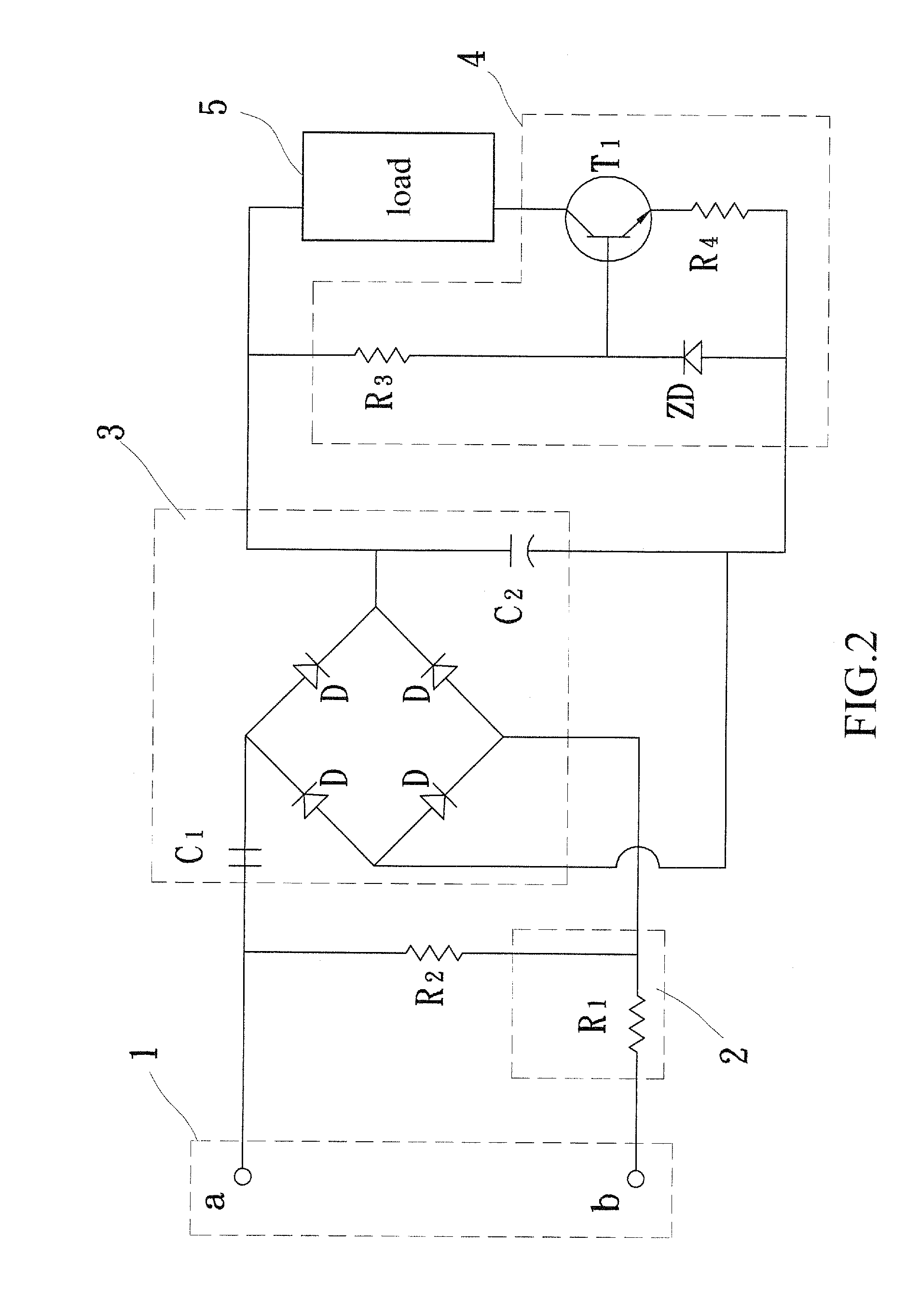
[0011]As shown in FIGS. 1 and 2, a power input stabilizing circuit according to an embodiment of the present invention mainly contains an impulse current suppressing circuit 2, a power input limiting circuit 3, and a constant current circuit 4.

[0012]As illustrated, power is introduced through power input terminals 1, and then passes through a first resistor R1 of the impulse current suppressing circuit 2. The power input limiting circuit 3 contains a non-polarity capacitor C1 and a rectifier circuit...


PUM


Abstract

The power input stabilizing circuit provides a first resistor at the input terminals to suppress impulse current. Then, the power passes through a power input limiting circuit including a non-polarity capacitor, a rectifier circuit formed by diodes, and a polarity capacitor so as to provide a current within a specific range to a load. A constant current circuit including a third resistor, a diode, a fourth resistor, and a transistor is then employed to stabilize the load current. The performance and durability of the electrical or electronic appliance using the power input stabilizing circuit are therefore enhanced significantly.

Description

TECHNICAL FIELD OF THE INVENTION[0001]The present invention generally relates to a power input stabilizing circuit, and especially relates to a power input stabilizing circuit capable of suppressing impulse current and stabilizing load current.DESCRIPTION OF THE PRIOR ART[0002]As electrical and electronic appliances are continuously driven to be even more compact and highly efficient, heat dissipation and power supply have become major design issues to the durability of these appliances. Conventionally, input power to the appliances undergoes voltage drop through parallel-connected discharge resistors and capacitors, rectification through diodes, and finally becomes applicable to a load of the appliance through a current limiting circuit. This approach avoids the use of a bulky transformer and effectively controls current / voltage within a specific range. However, it is still susceptible to spikes or current impulses when the appliance is turned on or off. These impulses usually woul...

Claims


Application Information

Patent Timeline
Patent Type & Authority Applications(United States)
IPC IPC(8): H02H7/125
CPCH02H9/005H02M7/05
Inventor WU, HUI-MINGWU, CHUNG-YANG
Owner WU HUI MING
Why Eureka
Try Eureka