Bidirectional DC/DC converter and control method thereof

A converter and switch tube technology, applied in the field of bidirectional DC/DC converter and its control, can solve the problems of affecting the safe operation of the circuit, the boost ratio needs to be improved, the inductor current ripple is large, etc.

Active Publication Date: 2021-03-16
SHANGHAI JIAO TONG UNIV
View PDF5 Cites 3 Cited by
  • Summary
  • Abstract
  • Description
  • Claims
  • Application Information

AI Technical Summary

Problems solved by technology

In order to achieve a high boost ratio and reduce the voltage stress of switching devices, switched capacitors are gradually introduced into bidirectional DC / DC converters, but the introduction of switched capacitors will bring inrush current, which will affect the safe operation of the circuit
[0004] Literature H.Ardi, A.Ajami, F.Kardan and S.N.Avilagh, "Analysis and Implementation of a Nonisolated Bidirectional DC–DC Converter With HighVoltage Gain," in IEEE Transactions on Industrial Electronics, vol.63, no.8, pp.4878 -4888, Aug.2016, doi:10.1109 / TIE.2016.2552139. A non-isolated bidirectional DC / DC converter is proposed, which has the advantages of high voltage conversion ratio, high efficiency, and simple control. The voltage stress is very large, which is 1 to 2 times that of the high-voltage side voltage, and the boost ratio needs to be improved, and the inductor current ripple is large

Method used


Image

  • Bidirectional DC/DC converter and control method thereof
  • Bidirectional DC/DC converter and control method thereof
  • Bidirectional DC/DC converter and control method thereof

Examples


Embodiment Construction

[0100] The embodiments of the present invention are described in detail below, and the present embodiments are implemented on the premise of the technical solution of the present invention, and detailed implementation methods and specific operating procedures are provided, but the protection scope of the present invention is not limited to the following implementation example.

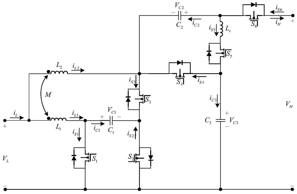
[0101] Such as figure 1 Shown is a circuit diagram of a bidirectional DC / DC converter according to an embodiment of the present invention.

[0102] Please refer to figure 1 , the bidirectional DC / DC converter of this embodiment includes: a switch tube, a capacitor, a coupling inductor, and a resonant inductor Lr; wherein, the switch tube includes: a first switch tube S1, a second switch tube S2, a third switch tube S3, a The four switch tubes S4, the fifth switch tube S5 and the sixth switch tube S6; the capacitors include: a first capacitor C1, a second capacitor C2 and a third capacitor C3. In thi...


PUM


Abstract

The invention discloses a bidirectional DC / DC converter and a control method thereof. The bidirectional DC / DC converter comprises a coupling inductor, six switching tubes, three capacitors and a resonant inductor, wherein the first end of the coupling inductor serves as a low-voltage side anode, the second end of the coupling inductor is connected with the first switching tube and the first capacitor, the third end of the coupling inductor is connected with the third switching tube, the fourth switching tube and the second capacitor, the first end of the first switching tube is connected withthe second switching tube and the third capacitor as a cathode, the second end of the first switching tube is connected with the first capacitor, the second end of the first capacitor is respectivelyconnected with the third switching tube and the second switching tube, the second end of the third switching tube is respectively connected with the fourth switching tube and the second capacitor, thesecond end of the second capacitor is respectively connected with the resonant inductor and the sixth switching tube, the second end of the fourth switching tube is respectively connected with the fifth switching tube and the third capacitor, the second end of the resonant inductor is connected with the fifth switching tube, and the second end of the sixth switching tube serves as a high-voltageside anode. The bidirectional DC / DC converter of the invention has the advantages of high voltage conversion ratio, small device voltage stress, small ripple current and the like.

Description

technical field [0001] The invention relates to the technical field of DC converters, in particular to a bidirectional DC / DC converter and a control method thereof. Background technique [0002] Bidirectional DC / DC converters have been widely used in new energy grid-connected systems and energy storage systems. In order to achieve a large voltage conversion ratio, the traditional bidirectional DC / DC converter often adopts the structure of a high-frequency isolation transformer, but the structure of the high-frequency isolation transformer is relatively complicated, and its volume and cost are relatively large. Although the traditional non-isolated bidirectional DC / DC converter has a simple structure, it also has disadvantages such as small voltage conversion ratio and large device voltage stress. The invention proposes a novel non-isolated bidirectional DC / DC converter topology, which has the characteristics of high voltage conversion ratio, less device voltage stress, and ...

Claims


Application Information

Patent Timeline
Patent Type & Authority Applications(China)
IPC IPC(8): H02M3/158H02M1/14
CPCH02M1/14H02M3/1582Y02B70/10
Inventor 高强梅军蔡旭
Owner SHANGHAI JIAO TONG UNIV
Why Eureka
Try Eureka