
Temperature-measurement probe

a temperature measurement and probe technology, applied in the field of apparatus, system and method for measuring can solve the problems of inaccuracy in estimating the temperature of the target si

Inactive Publication Date: 2011-06-30
WELCH ALLYN INC
View PDF74 Cites 22 Cited by
  • Summary
  • Abstract
  • Description
  • Claims
  • Application Information

AI Technical Summary

Benefits of technology

[0004]The invention provides for an apparatus, system and method for measurement of a temperature of a target site, such a human body site. The invention includes an intelligent probe that is configured to physically contact a target site and to communicate with a host device that can be implemented as a hand-held device or as a personal computer. The host device, such as a personal computer, can compute, store and display an accurate predicted temperature, or a measured temperature at thermal equilibrium of the target site. The host device is configured to interface with and adapt to each of a plurality of different intelligent temperature probes that each have unique and varied operating characteristics. A set of unique operating characteristics for each temperature probe is represented by information including a procedural model that is communicated between each respective temperature probe and the host device.

Problems solved by technology

Variations in the manufacture of the predictive thermometer may cause inaccuracies with respect to the estimating the temperature of the target site.

Method used


Image

  • Temperature-measurement probe
  • Temperature-measurement probe
  • Temperature-measurement probe

Examples


first embodiment

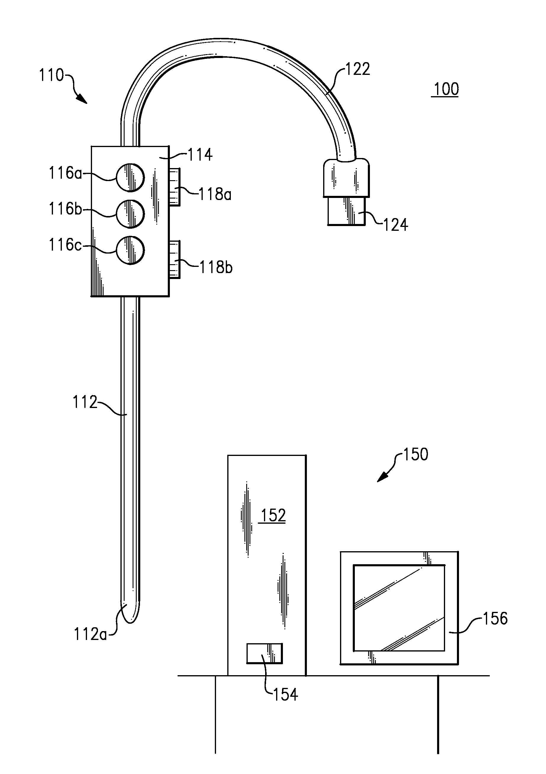
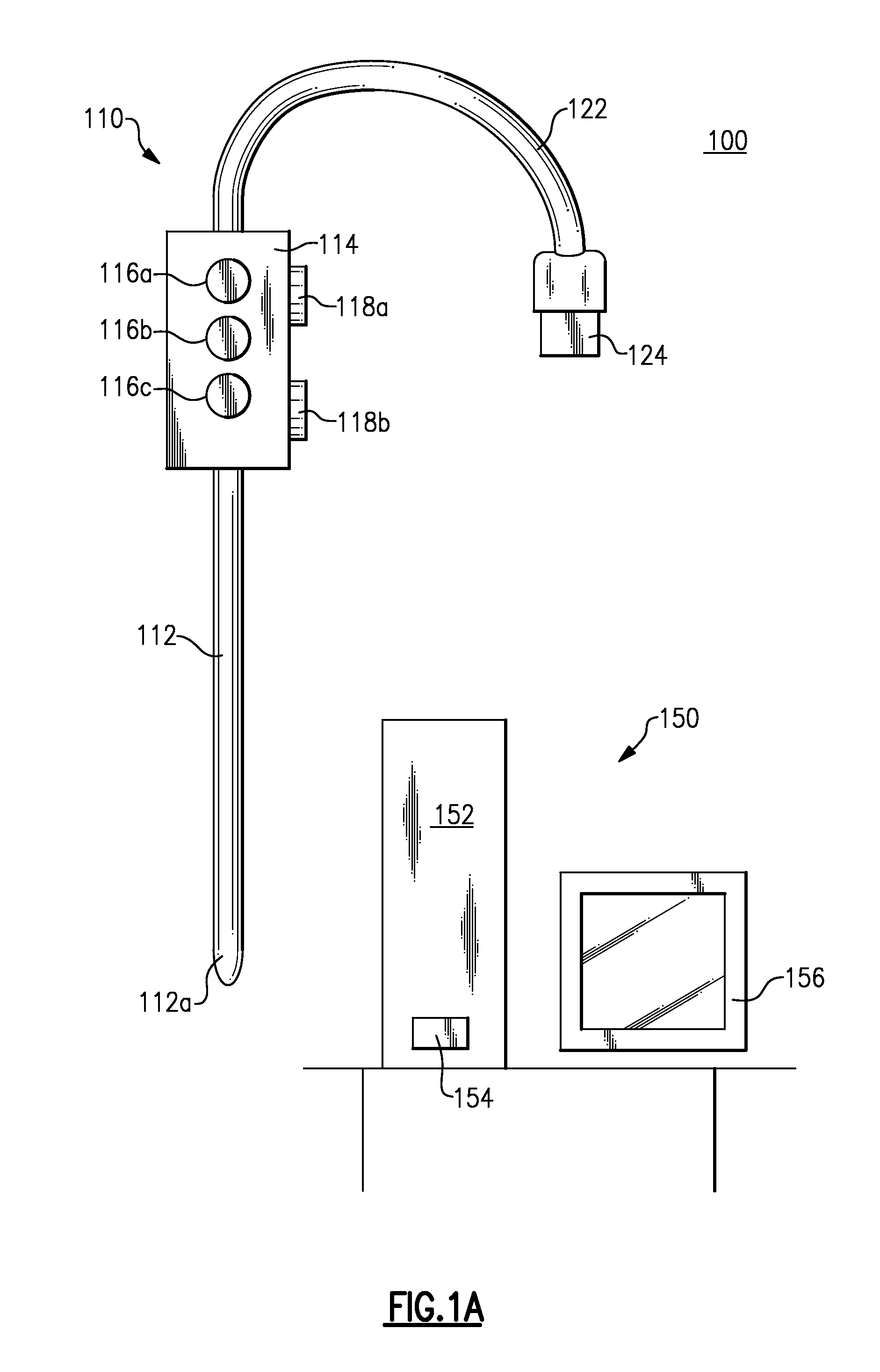
[0016]FIG. 1A illustrates a hand held and universal serial bus powered temperature-measurement probe device 110 and a host device 150 that is implemented as a personal computer. The temperature-measurement probe device 110, also referred to as a device 110, includes a probe portion 112, a handle portion 114, a power and data connection cable 122 and a power and data connector 124.

[0017]The probe portion 112, also referred to as a probe body 112, is an elongated member that is designed to be placed in physical contact with a target location, such as in contact with a human body site. The probe tip 112a is preferably made from temperature sensitive material, for example made from a metal alloy including such as stainless steel or aluminum. The probe portion 112 includes a probe tip 112a at a distal end located farthest from the handle portion 114 of the device 110.

[0018]The handle portion 114 is designed to be held within a hand of a user of the device 110. As shown, the handle portio...

second embodiment

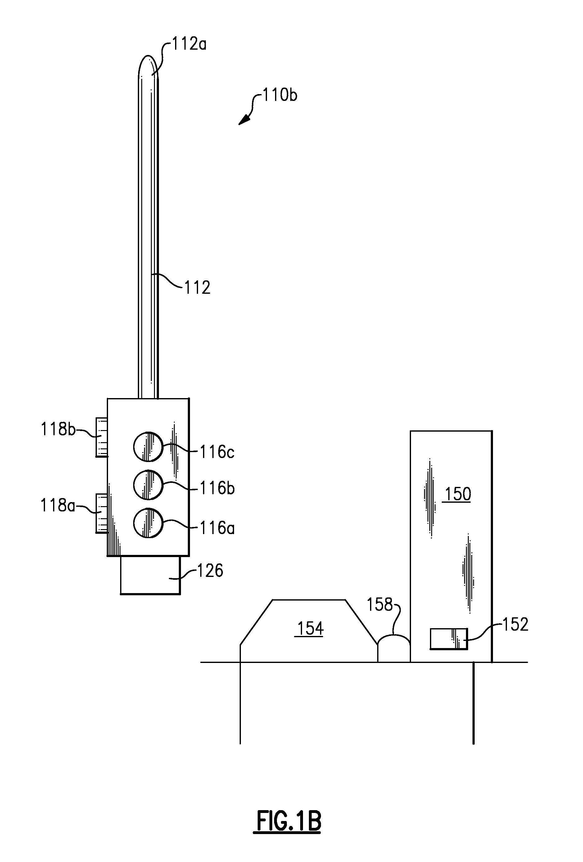
[0035]FIG. 1B illustrates the temperature-measurement probe device 110 that is designed to attached into a probe cradle 154. As shown, the probe cradle 154 is electrically connected to a personal computer 150 via a communications cable 158. The device 110b includes a connector 126 that is designed to be inserted into an upper side of the probe cradle 154. Upon being inserted, the device 110 electrically attaches to the probe cradle 154 for transfer of power and data between the host 150 and the device 110b via a communications channel established by the probe cradle 154 and communications cable 158.

[0036]Digital logic residing within the device 112 detects attachment to the probe cradle 154 and detachment from the probe cradle 154. In some embodiments, upon detachment of the device 110b from the probe cradle 154, the device 110b can initiate the heater and / or the execution of the temperature prediction algorithm separate from the pressing of any button 118a-118b. Upon attachment of ...


PUM

PropertyMeasurementUnit
temperatureaaaaaaaaaa
physical connectionaaaaaaaaaa

Abstract

An apparatus, system and method for temperature measurement of a target site, such a human body site. The invention includes an intelligent temperature probe configured to physically contact a target site and to communicate with a host device, which can be implemented as a hand-held device or as a personal computer. The host device can compute, store and display an accurate predicted temperature, or an actual temperature at thermal equilibrium, of the target site for each of a plurality of different intelligent temperature probes that each have unique and varied operating characteristics. A set of unique operating characteristics for each temperature probe is represented by information communicated between each respective temperature probe and the host device.

Description

CROSS REFERENCE TO PATENT APPLICATIONS INCLUDING RELATED SUBJECT MATTER[0001]This patent application includes subject matter that appears related to the subject matter that is included within U.S. Pat. No. 7,255,475, that is titled “Thermometry Probe Calibration Method”, and that was issued Aug. 14, 2007. The aforementioned patent is herein incorporated by reference in its entirety.FIELD OF THE INVENTION[0002]This invention relates to an apparatus, system and method for measurement of a temperature of a target site, such as a human body site. The invention includes an intelligent probe having a set of unique operating characteristics and that is configured to physically contact a target site and to communicate with a host device that can be implemented as a hand-held device or as a personal computer.BACKGROUND OF THE INVENTION[0003]A predictive thermometer includes a probe tip that is placed in physical contact with a target site, such as a human body site, for the purpose of measur...

Claims


Application Information

Patent Timeline
Patent Type & Authority Applications(United States)
IPC IPC(8): G01K7/00
CPCG01K1/022G01K13/002Y10T29/49117G01K1/02G01K7/22G01K1/024G01K7/42G01K13/20
Inventor MEYERSON, CRAIG M.QUINN, DAVID E.LANE, JOHN A.WAGNER, ANTHONY P.KINSLEY, MATTHEW J.MARTIN, SCOTT A.MULLIN, MATTHEW D.
Owner WELCH ALLYN INC
Learn More