Tooth extraction tool

a tooth extraction and tooth technology, applied in boring tools, medical science, dentistry, etc., can solve the problems of reducing the likelihood of fracturing the root and reducing the movement of the tooth

Inactive Publication Date: 2011-06-30
KING SAUD UNIVERSITY
View PDF40 Cites 8 Cited by
  • Summary
  • Abstract
  • Description
  • Claims
  • Application Information

AI Technical Summary

Problems solved by technology

Further, the apical pressure results in minimal movement of the tooth in an apical direction and exposure of the tooth socket by the break down in the periodontal ligament space.
In addition, the fulcrum, the center of the tooth's movement is placed more apically and decreases the likelihood of fracturing the root.

Method used


Image

  • Tooth extraction tool
  • Tooth extraction tool

Examples


Embodiment Construction

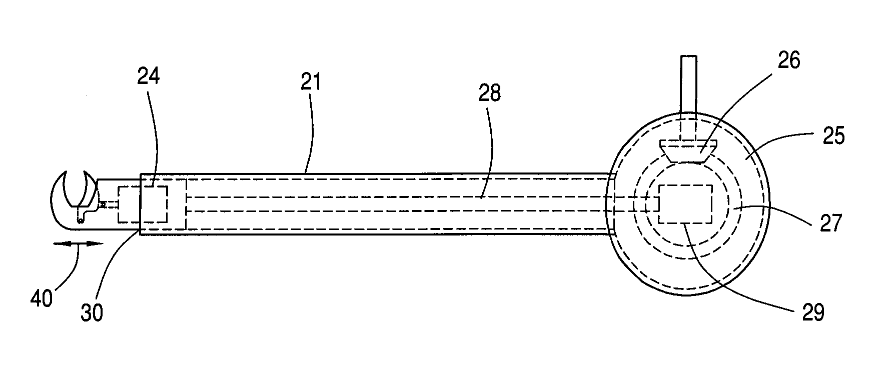
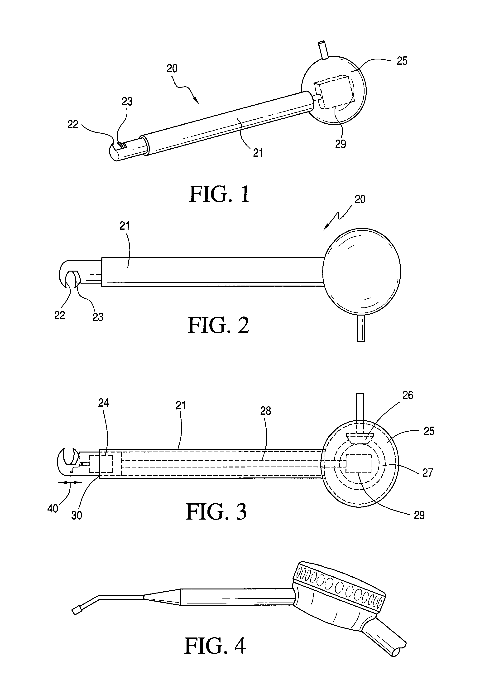
[0013]As shown in FIGS. 1 and 2, a tooth extraction tool 20 includes an elongated handle 21 and a pair of forceps or tooth engaging members at one end of the handle. The forceps include two tooth engaging members 22 and 23 one of which is fixed and the other of which is movable to tightly grip a tooth to be removed between the two members. The first of the tooth engaging members 22 is fixed while the second member 23 moves toward and away from the first member 22 to tightly grip a tooth (not shown) that is to be removed. The second removable tooth engaging member is moved by a fluid actuated piston 24 to tightly grip the tooth and subsequently after removal to release the tooth.

[0014]The tooth engaging members 22 and 23 grip a tooth to be removed in response to the fluid activated piston 24. The fluid may be applied hydraulically or pneumatically. As shown, the tooth extraction tool 20 also includes a housing 25 at an opposite end of the handle 21. The housing 25 encases a pair of c...


PUM


Abstract

A tooth extracting tool including an elongated handle and a pair of tooth engaging members extending out of one end of the handle and a pneumatic or hydraulic piston for tightly gripping the tooth to be extracted between the pair of tooth engaging members. The tool also includes a mechanism for subjecting the grasped tooth to linear oscillation at an opposite end of the handle and for limiting the back and forth linear movement of the tooth to between about plus or minus 5 mm.

Description

FIELD OF THE INVENTION[0001]This invention relates to a tooth extraction tool and more particularly to a tooth extraction tool that subjects a tooth to be extracted to linear oscillation.BACKGROUND FOR THE INVENTION[0002]Tooth extraction tools are will known and have been in use for many years. For example, a U.S. Pat. No. 2,777,198 of Wallace discloses a tooth extraction device which provides a minimum danger of injury to the tooth or to the jaw of a patient. The device uses a pair of forceps which are connected to an arm. Then after the forceps are engaged with a tooth, a motor is activated to transmit a high frequency vibration through the forceps to the tooth. The vibration causes the breaking down of the tissue surrounding the tooth so that slight upward or downward movement of the arm removes the tooth from an upper or lower dental arch.[0003]A more recent U.S. Pat. No. 4,230,454 of Lococo discloses a tooth extractor that utilizes a vice type grip member having a joint member ...

Claims


Application Information

Patent Timeline
Patent Type & Authority Applications(United States)
IPC IPC(8): A61C3/14
CPCA61C3/14
Inventor DARWISH, SAIED MOHAMED HASSANDAWOOD, ABDEL NASSERDARWISH, GAMAL MOHAMED HASSANAL-AHMARI, ABDULRAHMAN M.
Owner KING SAUD UNIVERSITY
Why Eureka
Try Eureka