Cartridge

Active Publication Date: 2011-06-30
BROTHER KOGYO KK
View PDF4 Cites 32 Cited by
  • Summary
  • Abstract
  • Description
  • Claims
  • Application Information

AI Technical Summary

Benefits of technology

[0011]In the above case, however, a space for providing the guide wall is necessary in the apparatus body. This increases the size of the apparatus body. Moreov

Problems solved by technology

In the above case, however, a space for providing the guide wall is necessary in the apparatus body.
This increases the size of the apparatus body.
Moreover,

Method used


Image

  • Cartridge
  • Cartridge
  • Cartridge

Examples


Example

6. SECOND EMBODIMENT

[0087]Referring to FIG. 14, the ridges 43 of the inserted portion 40 may be twisted in the direction of rotation.

[0088]Specifically, in a second embodiment of the present invention, the ridges 43 may be twisted such that the ends thereof near the body 42 are positioned on the downstream side in the direction of rotation with respect to the ends thereof near the stopper 41, thereby forming helical splines.

[0089]As shown in FIGS. 15 and 16, in correspondence with the ridges 43, the receiving grooves 34 formed in the surface defining the through-hole 33 of the flange member 23 may be also twisted such that the ends thereof near the projecting portion 32 are positioned on the downstream side in the direction of rotation with respect to the ends thereof near the press-fitted portion 31.

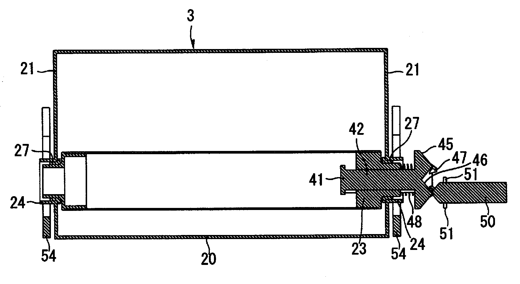
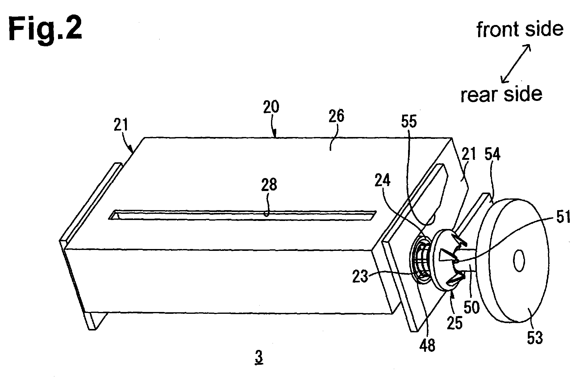
[0090]To summarize, in the second embodiment described above, the photoconductor drum 7 may have at one end thereof the cylindrical flange member 23. The drum-side coupling 25 may have ...


PUM


Abstract

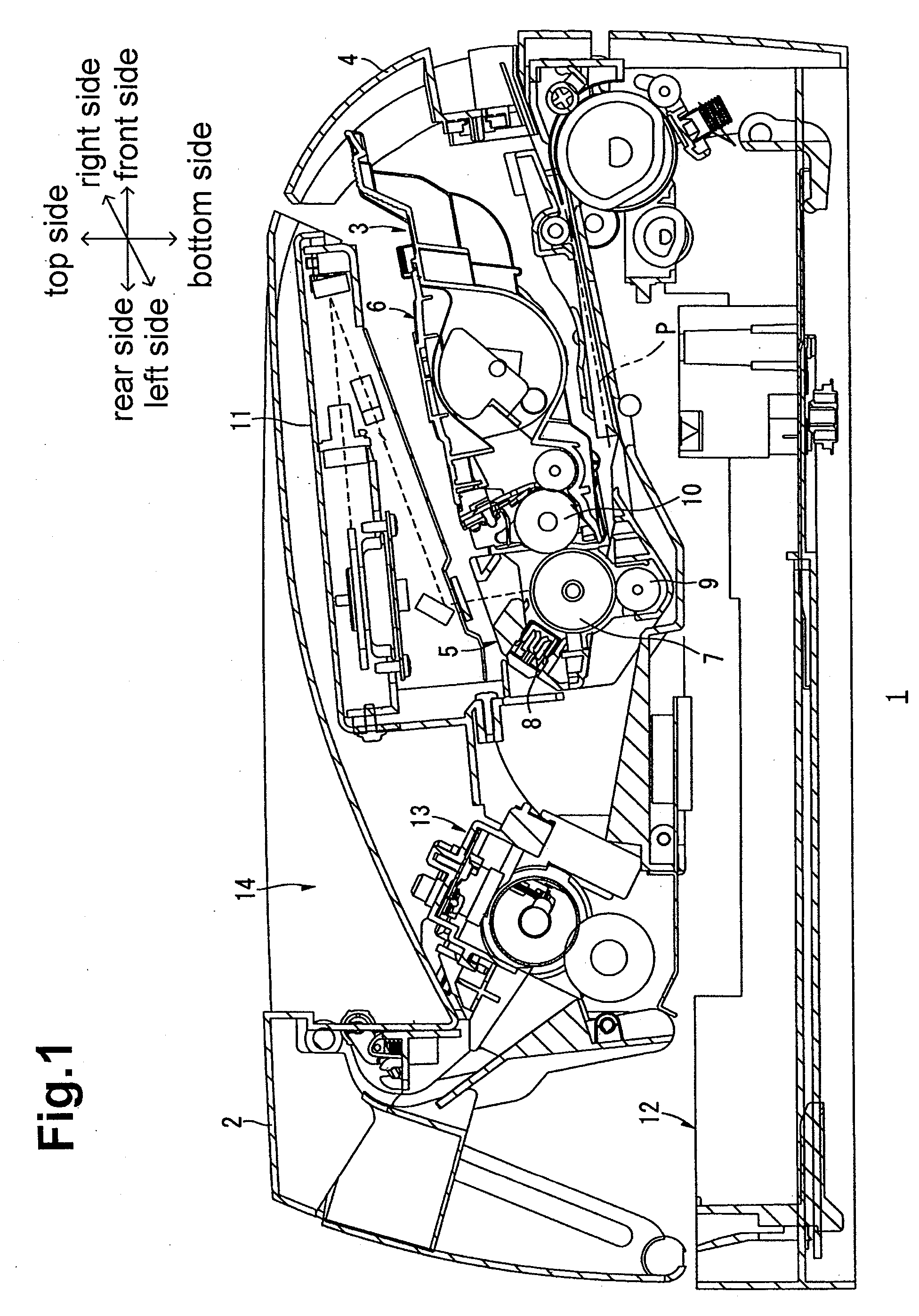
A cartridge includes a casing, a rotatable member rotatably supported by the casing, a protruding member configured to advance and retract in directions parallel to an axis of rotation of the rotatable member, and an urging member configured to urge the protruding member to advance in an advancing direction. The protruding member has a perticular sloping surface configured to be contacted in a direction orthogonal to an axis of rotation of the protruding member when the cartridge is mounted. The perticular sloping surface slopes with respect to directions parallel to and orthogonal to the axis of rotation of the protruding member.

Description

CROSS-REFERENCE TO RELATED APPLICATIONS[0001]The present application claims priority to and the benefit of Japanese Patent Application No 2009-293468, which was filed on Dec. 24, 2009, the disclosure of which is incorporated herein by reference in its entirety.BACKGROUND OF THE INVENTION[0002]1. Field of the Invention[0003]The present invention relates to a cartridge mountable into and demountable from the body of an image-forming apparatus.[0004]2. Description of the Related Art[0005]It is known that some image-forming apparatuses, such as laser printers, include cartridges that are demountably mounted in the bodies thereof (see Japanese Unexamined Patent Application Publication No. 2007-79139, for example).[0006]Such cartridges house rotatable members such as a photoconductor drum on which an electrostatic latent image is to be formed and a development roller that supplies toner onto the peripheral surface of the photoconductor drum. In a case of a development cartridge, a rotatab...

Claims


Application Information

Patent Timeline
IPC IPC(8): F16D3/06G03G15/06
CPCG03G2221/1657G03G21/1864
Inventor OKABE, YASUSHI
Owner BROTHER KOGYO KK
Why Eureka
Try Eureka