
Reduced Ambient Fields Error In A Magnetoelastic Torque Sensor System

a sensor system and ambient field technology, applied in the field of reducing ambient field error in the magnetoelastic torque sensor system, can solve problems such as false torque readings, and achieve the effect of reducing the amount of errors

Inactive Publication Date: 2011-07-07
SMTS
View PDF4 Cites 30 Cited by
  • Summary
  • Abstract
  • Description
  • Claims
  • Application Information

AI Technical Summary

Benefits of technology

[0008]The present invention was devised to provide a magnetoelastic torque transducer by arranging the magnetic torque sensors in a manner and signal process means that minimizes the amount of error caused by ambient magnetic fields.
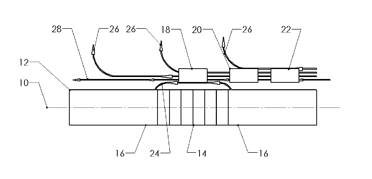
[0014]By subtracting output signals of the third set of secondary sensor or sensors from that of the second set, the resulting signal (S2−S3) is the difference of the non-uniform fields effect on the third set of secondary sensor or sensors and the second set of secondary sensor or sensors, because they have the same output signals respond to both the fields cause by torque and uniform ambient fields. This signal (S2−S3) has a known relationship to the difference of effects of non-uniform fields on primary and second set of field sensors once the torque sensor system is known, so it can be used to compensate for the effects of non-uniform ambient fields on the primary set of field sensor or sensors.

Problems solved by technology

In practical usages, a torque sensor is exposed to ambient magnetic fields, there are numerous types of ambient magnetic fields, and these ambient sources can combine with torque-induced magnetic fields and lead to false torque reading.

Method used


Image

  • Reduced Ambient Fields Error In A Magnetoelastic Torque Sensor System
  • Reduced Ambient Fields Error In A Magnetoelastic Torque Sensor System
  • Reduced Ambient Fields Error In A Magnetoelastic Torque Sensor System

Examples


Embodiment Construction

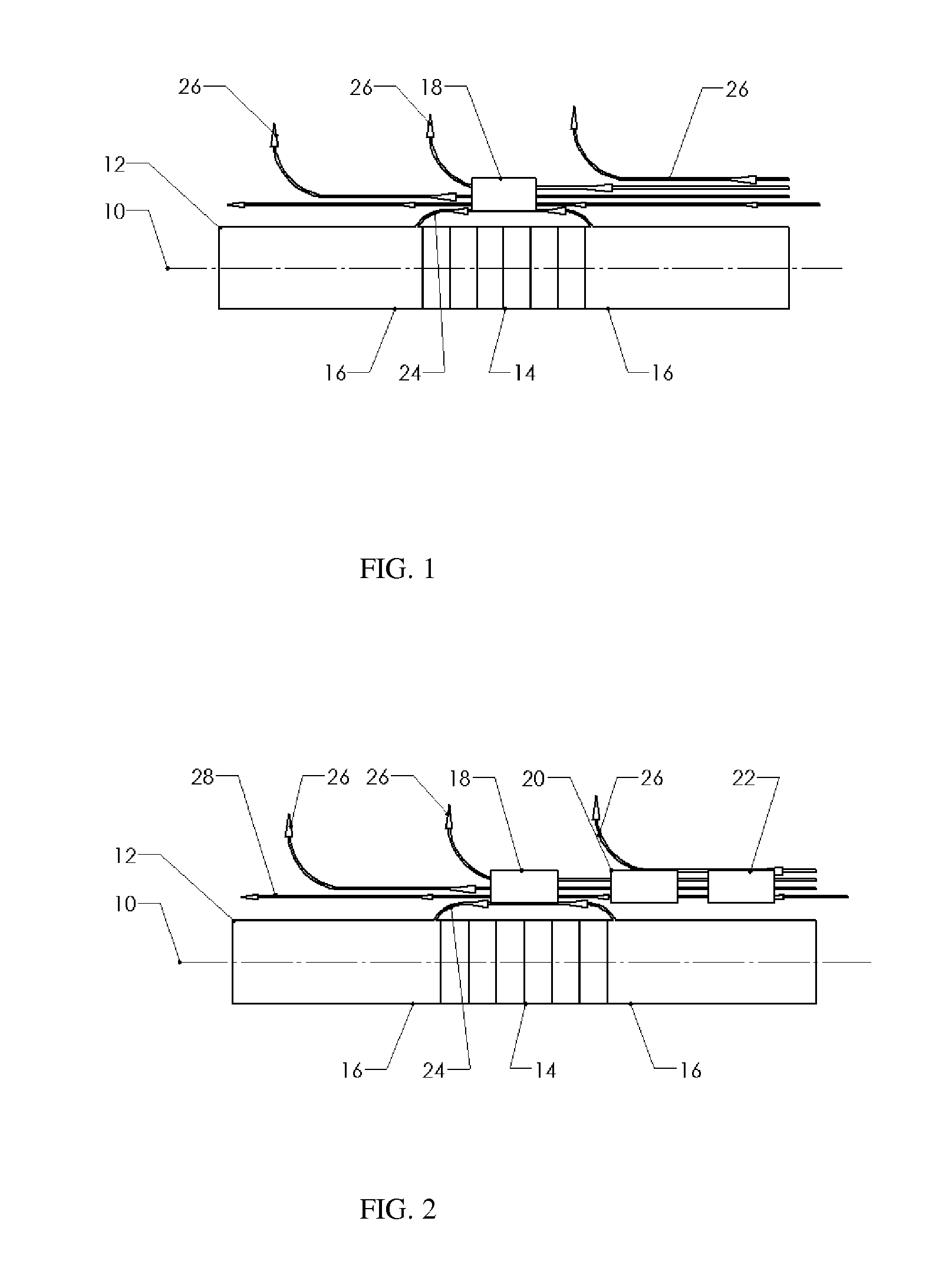
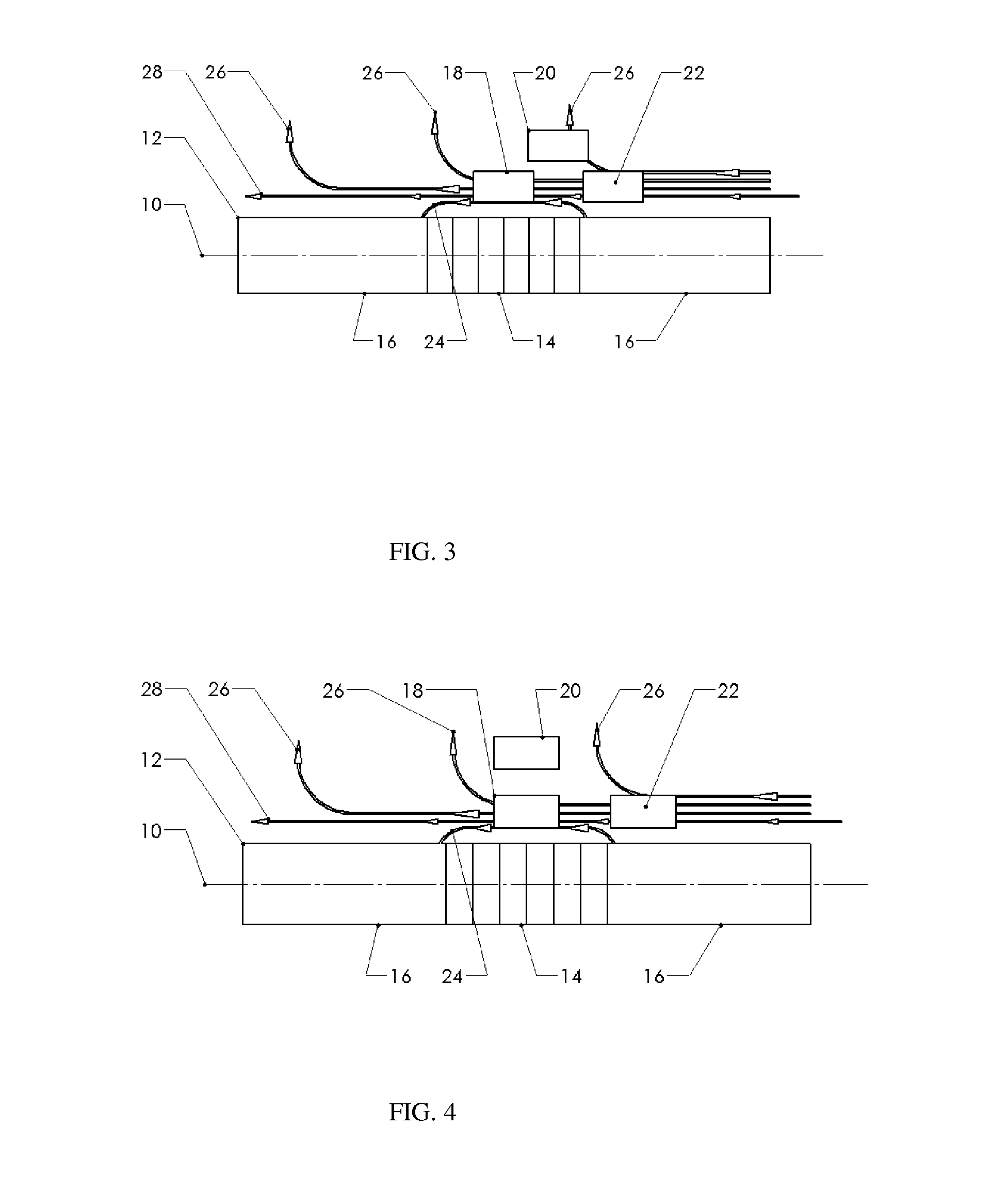
[0025]FIG. 2 illustrates a preferred embodiment of a magnetoelastic torque sensing apparatus in accordance with the invention. In this exemplary embodiment, the torque carrying shaft 12 having a torque T applied about a central longitudinal axis 10, the shaft 12 has an magnetoelastically active portion 14, one set of primary field sensor or sensors 18 is placed approximate to this magnetoelastically active portion 14 to detect the magnetic flux 24 arise from applied torque, and one set of secondary field sensor or sensors 20, is placed next to primary set of field sensor or sensors 18 axially, another set of secondary field sensor or sensors 22 is placed in the same direction farther away axially so both the second and third sets of secondary sensor or sensors on the same side of the primary set of field sensor or sensors 18. Sensors 20 and 22 are disposed in such a way that they are far away enough from magnetoelastically active portion 14 to avoid the magnetic flux 24 dependent on...


PUM


Abstract

An improved magnetic torque transducer involves a method and apparatus for compensating effects of uniform and / or non-uniform magnetic sources by placing three sets of magnetic field sensors around a shaft with at least one magnetized zone. The set of primary magnetic field sensor or sensors is placed proximate to the magnetized zone, both the second and third sets of secondary magnetic field sensors being placed by pre-determined distances to the primary set of magnetic field sensor or sensors, so that primary field sensors always in a position with higher magnetic field strength arise from applied torque than that of secondary sensors. And a method is developed to use the second and third signals from secondary sensors to adjust the primary signal to compensating for the effects of the uniform and / or non-uniform ambient magnetic field sources.

Description

CROSS-REFERENCE TO RELATED APPLICATIONS[0001]Not ApplicableFEDERALLY SPONSORED RESEARCH[0002]Not ApplicableSEQUENCE LISTING OR PROGRAM[0003]Not ApplicableFIELD OF THE INVENTION[0004]This invention relates to the field of using magnetic sensors to measure torque applied to a shaft. More particularly, the invention is related to systems, methods, and apparatus involving sensors and circuits that reduce ambient magnetic fields effects while measuring torque-induced magnetic fields.BACKGROUND OF THE INVENTION[0005]Magnetic torque sensors are known in the art. Many versions of this type of magnetoelastic torque sensor have been proposed and described in a plurality of publications and patent specifications. These sensor systems are contactless in that a transducer element generating a torque-dependent magnetic field rotates with a shaft. The torque-dependent magnetic field is sensed by a sensor or sensor assembly that is not in contact with the rotating parts.[0006]In practical usages, a...

Claims


Application Information

Patent Timeline
IPC IPC(8): G01L3/10
CPCG01L3/102
Inventor WENG, WENSHENG
Owner SMTS
Learn More