
Heater apparatus

a technology of heaters and heaters, applied in the field of heaters, can solve the problems of increasing the risk of blown out flames in windy locations, increasing the risk of exposed flames being blown out, and becoming quite hot, so as to achieve the effect of improving safety and maintaining a lit flam

Inactive Publication Date: 2011-07-07
DIVENTURA LOUIS
View PDF2 Cites 20 Cited by
  • Summary
  • Abstract
  • Description
  • Claims
  • Application Information

AI Technical Summary

Benefits of technology

[0008]The present invention relates to a heater apparatus and in particular to an outdoor gas type heater. The heater includes a triangular frame forming a lower housing. The housing includes a burner and a fuel tank with an access door providing access for changing the fuel tank and for actuating the burner controls. The frame is generally configured as a triangular frame with upright members extending at each of three corners of the triangular profile formed by the frame. The upright members generally include an outer rectangular support portion providing rigidity and structural integrity to the frame. A transparent tube extends upward from the housing above the burner and extends to a top cover. Protective grates attach to the upright members and provide protection around the transparent tube. The tube extends the length of the frame to above the top of the protective grate members and provides a visually glowing appearance along its entire length between the cover and the lower housing when the flame is lit. The tube also provides for more reliably maintaining a lit flame and improving safety at the top cover.

Problems solved by technology

Moreover, some heaters include guards that extend upward about the tube to keep hands and other body parts from touching the tube, which may become quite hot.
Such heaters still have some drawbacks as the flame may often flare above the top of the tube and deflects outward to create a potential safety hazard with the flame exposed.
The exposed flame is therefore at a greater risk of being blown out in windy locations.
In addition, the guards have exposed edges that may provide a safety hazard and may not provide desired strength and support.
Moreover, such heaters have a housing that requires removal of a panel to access the fuel tank so that changing the fuel tank is a time consuming task.

Method used


Image

  • Heater apparatus
  • Heater apparatus
  • Heater apparatus

Examples


first embodiment

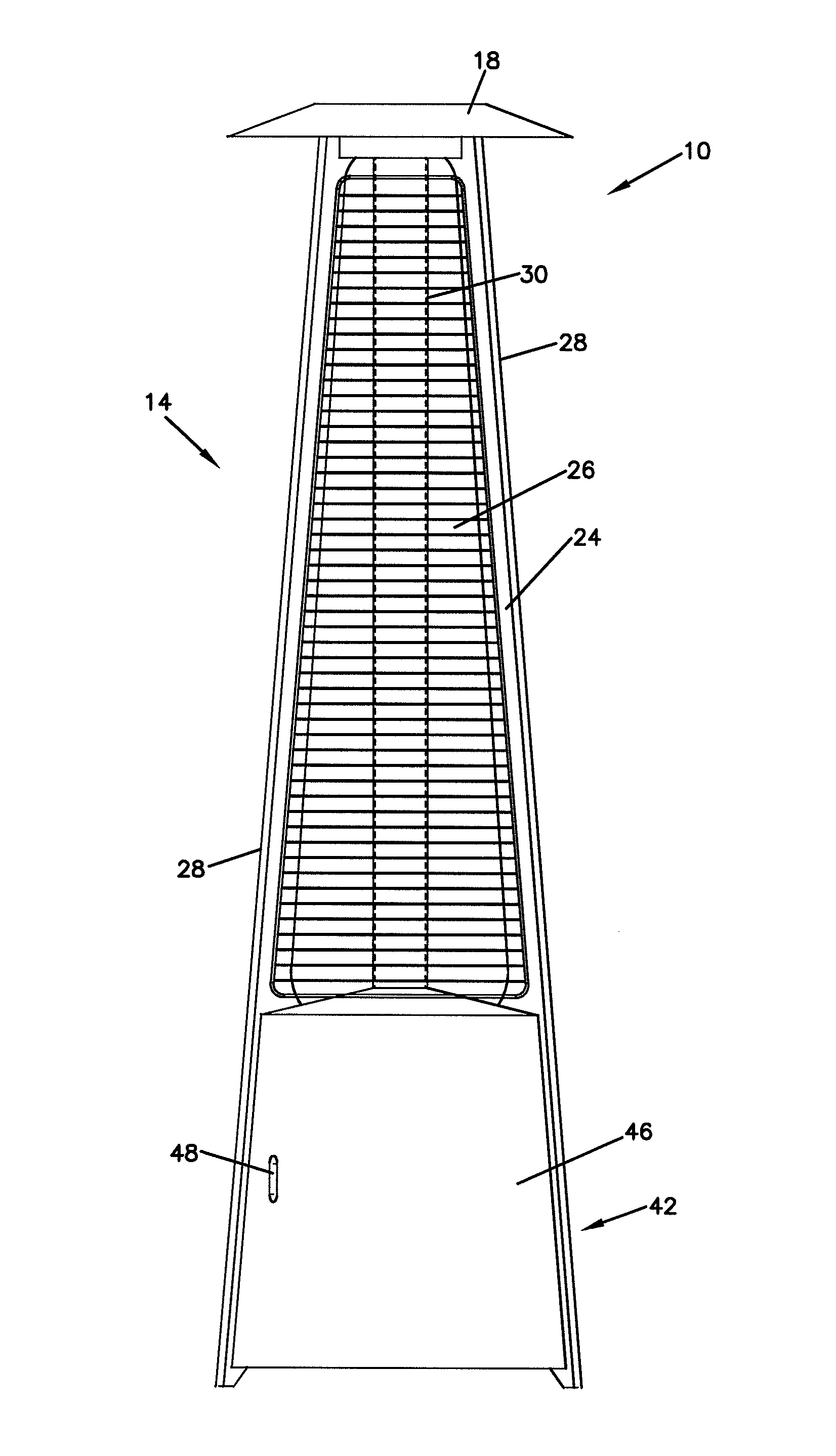
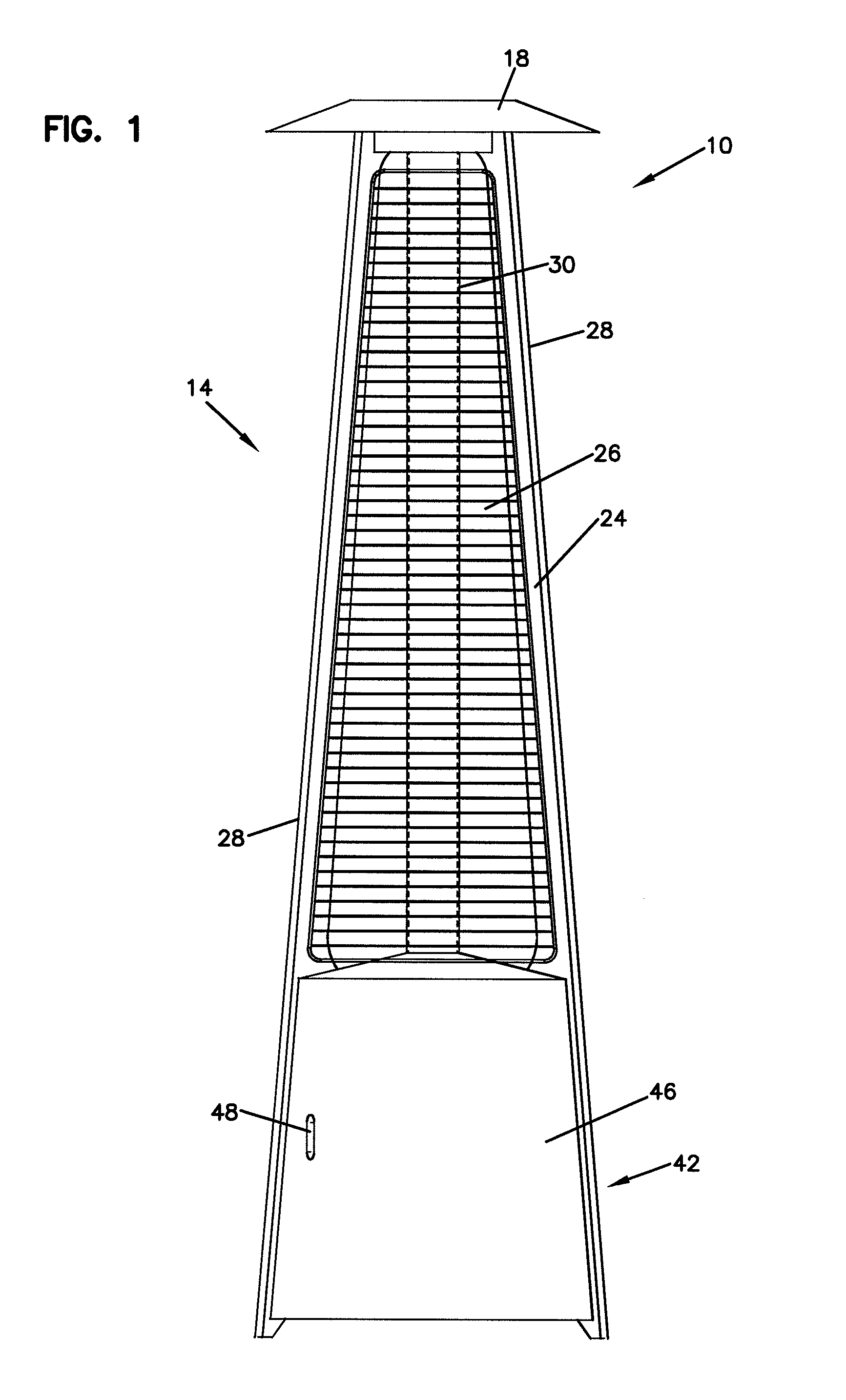
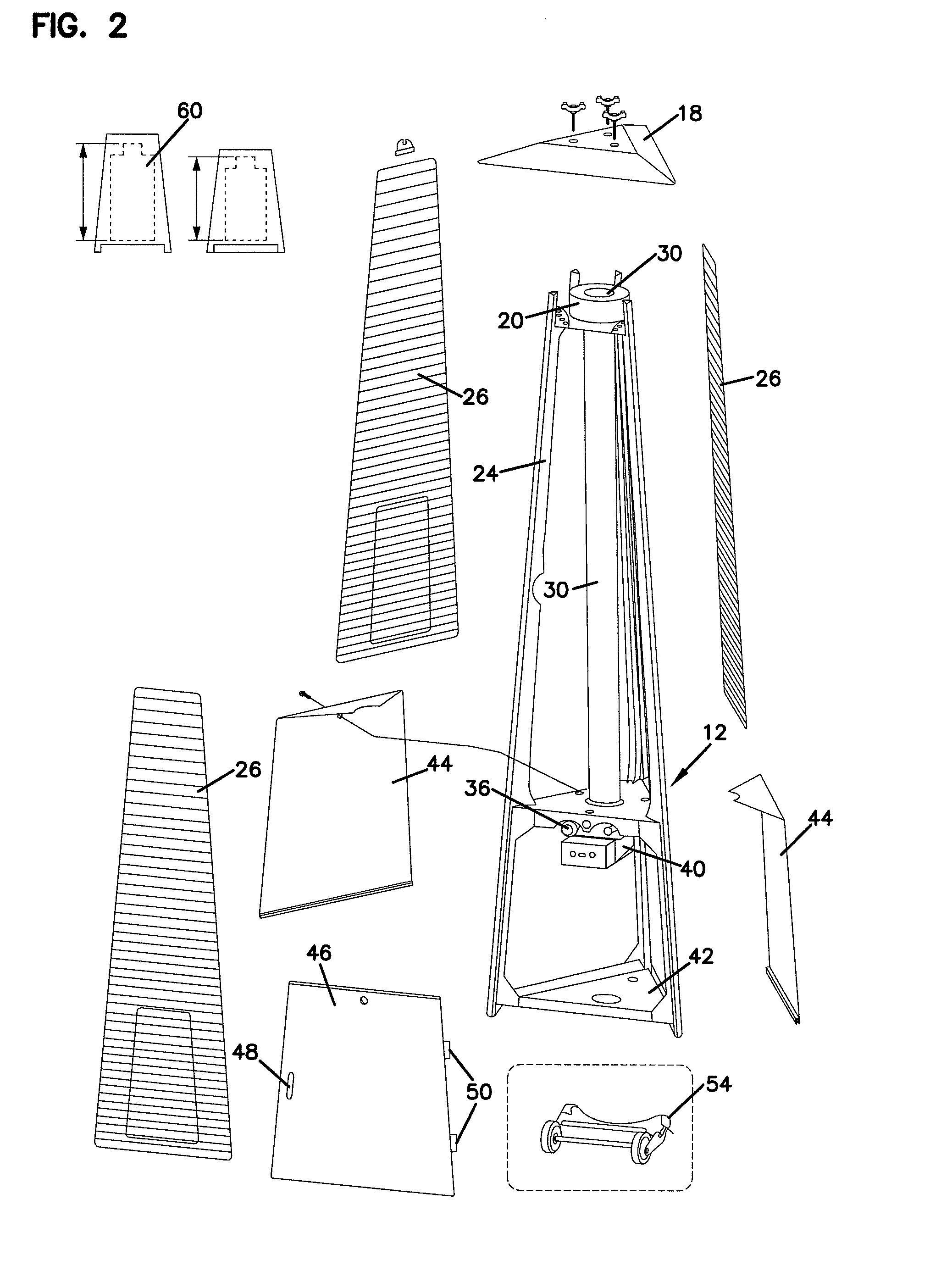
[0026]Referring now to the drawings and in particular to FIGS. 1 and 2, there is shown a portable outdoor heater apparatus, generally designated 10. The heater 10 includes a burner assembly, generally designated 12, as shown in FIG. 2. The burner assembly 12 provides a flame that extends upward and radiates through an emitting assembly 14. A top cover 18 extends above the emitting assembly 14. A lower housing 42 retains the burner assembly 12 and a refillable and interchangeable fuel tank 60, such as a conventional propane tank. Frame upright portions 24 extend at the three corners to support the cover 18 and protective grills 26. The frame members 24 form a frame having substantially triangular profile with an upright member 24 at each of the three corners of the triangle. Each of the frame upright members 24 includes a square corner support portion 28 providing additional rigidity and structural integrity.

[0027]The frame members 24 extend from the top of the lower housing 42. The ...

second embodiment

[0028]a portable outdoor heater apparatus is shown in FIGS. 3 and 4 generally designated 110. The heater 110 includes a burner assembly, generally designated 112, as shown in FIG. 6-8. The burner assembly 112 provides a flame that extends upward and radiates through an emitting assembly 114. A top deflector or cover 118 extends above the emitting assembly 114. A lower housing 142 retains the burner assembly 112 and a refillable and interchangeable fuel tank 60, such as a conventional propane tank. Frame upright portions 124 extend at the three corners to support the top cover 118 and protective grills 126. The frame members 124 form a frame having substantially triangular profile with an upright member 124 at each of the three corners of the triangle

[0029]The frame members 124 extend from the top of the lower housing 142. The housing 142 includes panels 144 on two sides of the housing 142 and an access door which is removed for clarity in FIGS. 3 and 4 on the third side. In a prefer...


PUM


Abstract

A portable heater includes a housing having an access door providing for receiving a fuel tank within the housing. The access door provides for insertion and removal of the fuel tank through the door. A burner within the housing is connected to the fuel tank and emits a flame above the housing. A vertical transparent tube extends above the burner and encompasses the flame along an entire height of the tube. A protective grill surrounds the tube and extends at least as far as the top of the protective grill. An upper cover assembly mounts to the top of the protective grill. The flame is enclosed extending up the tube along the entire height of the tube and creates a glowing vertical element from the housing to the cover.

Description

BACKGROUND OF THE INVENTION[0001]1. Field of the Invention[0002]The present invention is directed to a heater apparatus and in particular to a heater apparatus having a vertical tube containing a flame exposed along its length and extending from a bottom base to a top cover.[0003]2. Description of the Prior Art[0004]Outdoor patio type heaters have become commonplace and are widely used for providing radiant heat. Such heaters typically use a gas for fuel such as propane. Well known configurations for outdoor heaters typically include a burner connected to a portable refillable fuel tank at a bottom portion of the heater. The burner emits a flame that is deflected downward by a top cover on the heater. Heat is therefore deflected and radiated outward from the heater. Such heaters have an advantageous configuration as the flame is raised upward above users' normal seated position so that the heaters may be particularly well suited for placement for outdoor dining or where persons may ...

Claims


Application Information

Patent Timeline
Patent Type & Authority Applications(United States)
IPC IPC(8): F24C1/00F23N5/00
CPCF23D14/14F23D14/34F23D2212/00F24C3/14F23D2900/14122F23M2900/05004F23M2900/09062F23D2900/14121F23D14/151F23D14/148F24C3/042
Inventor DIVENTURA, LOUIS
Owner DIVENTURA LOUIS
Learn More