Method and apparatus for increasing therapy compliance

a technology of compliance and therapy, applied in the direction of burners, respirators, combustion types, etc., can solve the problem of limited evidence that these technology-centric advances have any impact on complian

Active Publication Date: 2011-07-07
FISHER & PAYKEL HEALTHCARE LTD
View PDF36 Cites 32 Cited by
  • Summary
  • Abstract
  • Description
  • Claims
  • Application Information

AI Technical Summary

Benefits of technology

[0008]Thus, the user-friendliness of a device may be important in improving compliance. Similarly, a device that is aesthetically pleasing may promote interaction and reduce cognitive distance as a barrier to therapy. This interaction between the aesthetics and the objective elements of treatment has been described in the dual process model of Leventhal H et al., The impact of communications on the self-regulation of health beliefs, decisions, and behavior, Health Education Behavior 1983; 10(1): 3-29. The theory states that the quality (emotional elements such as aesthetics) and clarity (cognitive elements such as ease of use) of a medical message, such as in the interaction with a medical device, can determine a patient's adherence.
[0009]Historically, to improve compliance, CPAP designers and manufacturers have focused on technological improvements, such as pressure modification and humidification. However, there is limited evidence that these technology-centric advances have any impact on compliance. Instead, improved user perception of treatment may lead to improved compliance with that treatment. It is believed that, through making the device more aesthetically pleasing and easy to use, the patient is more likely to comply with treatment.
[0010]Thus, a device has been designed to include means for improving the user-friendly nature of the device while also improving the aesthetics of the device.
[0012]In some configurations, a positive airway pressure device is configured to improve patient compliance by providing an improved user-friendliness and by reducing cognitive distance as a barrier to therapy. The positive airway pressure device comprises a housing comprising an outer surface. The outer surface comprises a front surface, a first side surface and a second side surface extending rearward from the front surface. A smooth contour is formed by the front surface, the first side surface and the second side surface. A control knob and a control display are positioned on the front wall. The control display comprises a clock display and a smiley face shaped indicator. A blower unit is disposed within the housing with an inlet to the blower unit being fluidly connected to ambient air and extending through at least one of the front wall, the first side wall, and the second side wall. A humidification compartment also is disposed within the housing. An internal power supply is positioned within the housing.
[0016]It is an object of the present invention to provide a breathing assistance apparatus which goes some way to overcoming the abovementioned disadvantages or which at least provides the public or industry with a useful choice.

Problems solved by technology

However, there is limited evidence that these technology-centric advances have any impact on compliance.

Method used


Image

  • Method and apparatus for increasing therapy compliance
  • Method and apparatus for increasing therapy compliance
  • Method and apparatus for increasing therapy compliance

Examples


Embodiment Construction

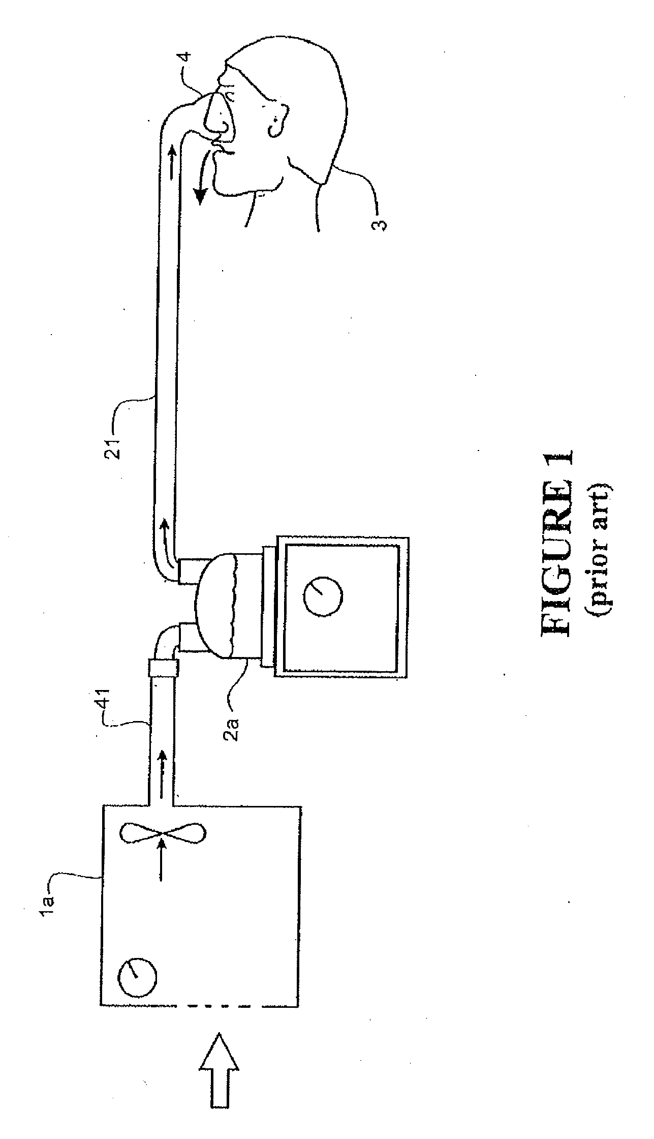
[0041]A schematic view of a user 3a receiving air from a known (prior art) modular assisted breathing unit and humidifier system is shown in FIG. 1. Pressurized air is provided from an assisted breathing unit or blower 1a via a conduit 41 to a humidifier chamber 2a. Humidified, • heated and pressurized gases exit the humidifier chamber 2a via a conduit 21, and are provided to the patient or user 3 via a user interface 4. The user interface 4 shown in FIG. 1 is a nasal mask, covering the nose of the user 3. However, it should be noted that in systems of these types, a full face mask, nasal cannula, tracheostomy fitting, or any other suitable user interface could be substituted for the nasal mask shown.

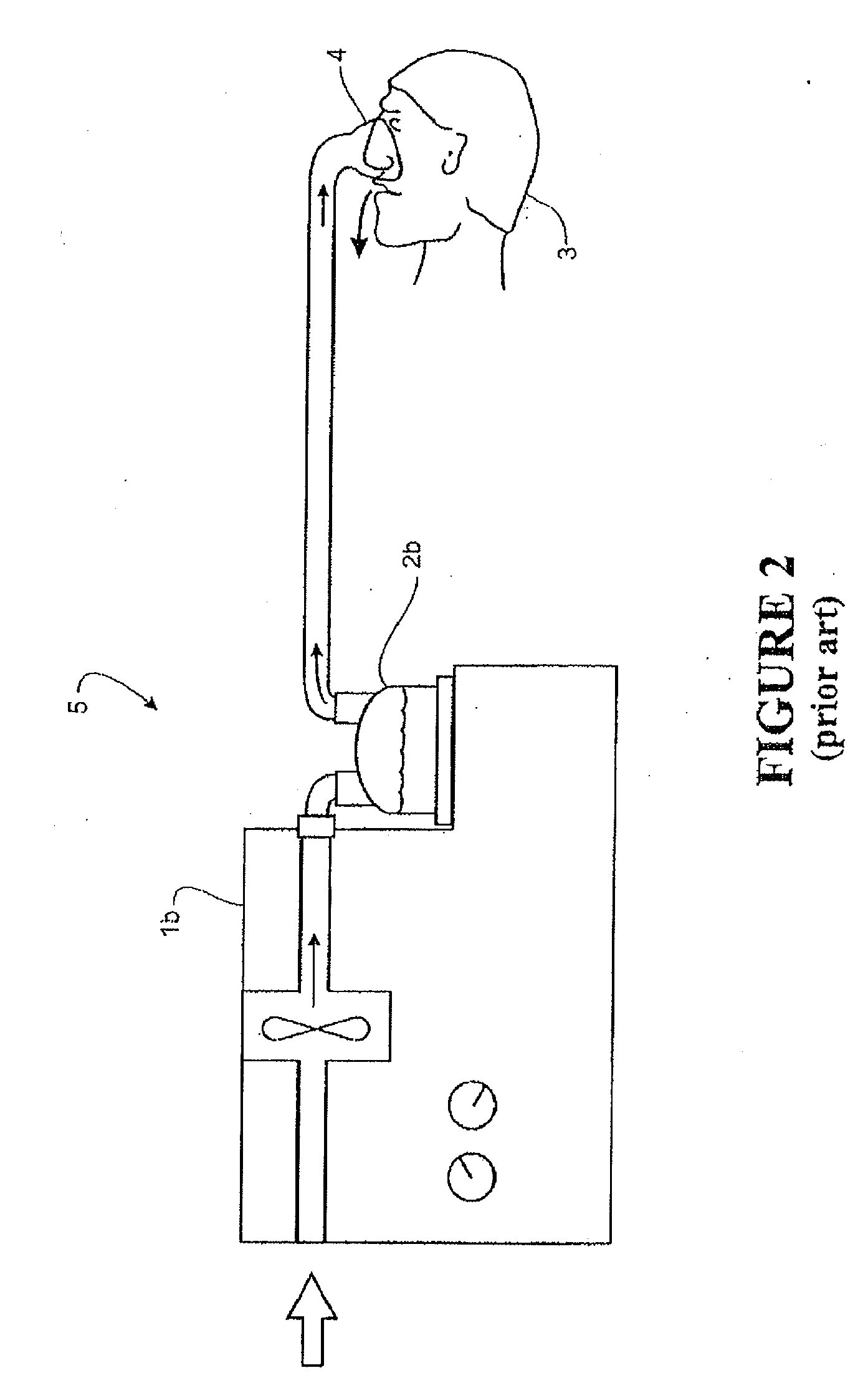
[0042]A schematic view of the user 3 receiving air from a known, prior art integrated blower / humidifier unit 5 is shown in FIG. 2. The system operates in the same manner as the modular system shown in FIG. 1, except that humidifier chamber 2b has been integrated with the blower unit 1b ...


PUM


Abstract

A breathing assistance unit for providing pressurized heated humidified air at to a user is configured to increase user compliance. The breathing assistance unit comprises means for generating positive emotional and cognitive states of a user about the therapy.

Description

CROSS-REFERENCE TO RELATED APPLICATIONS[0001]This application is a continuation in part of U.S. patent application Ser. No. 12 / 513,752, filed on Oct. 14, 2009, which claims priority under 35 U.S.C. §371 of PCT Application No. PCT / NZ2007 / 00328, filed on Oct. 31, 2007, which claims the priority benefit of New Zealand Application No. 560235, filed on Jul. 30, 2007 and U.S. Provisional Application No. 60 / 864,501, filed on Nov. 6, 2006, each of which is hereby incorporated by reference in its entirety.[0002]This application hereby incorporates by reference the entirety of the following applications: (1) U.S. Provisional Patent Application No. 61 / 084,322, which was filed on Jul. 29, 2008; (2) U.S. Provisional Patent Application No. 61 / 173,656, which was filed on Apr. 29, 2009; (3) U.S. Provisional Patent Application No. 61 / 184,379, which was filed on Jun. 5, 2009; (4) U.S. Provisional Patent Application No. 61 / 250,186, which was filed on Oct. 9, 2009; (5) U.S. Provisional Patent Applicati...

Claims


Application Information

Patent Timeline
Patent Type & Authority Applications(United States)
IPC IPC(8): A61M16/16
CPCA61M16/0066A61M16/16A61M2205/3606A61M2205/362A61M16/109A61M2205/502A61M2209/06A61M16/1075A61M2205/3653A61M16/107A61M16/0816A61M2205/21A61M16/1095A61M16/10A61M2205/36A61M39/1055A61M2039/1022A61M2039/1033
Inventor POTHARAJU, VENKATA SUBBARAOSTANTON, CHRISTIE JAYNESALMON, ANDREW PAUL MAXWELLSUN, YI-CHENGBRISCOE, HAYDENFREW, SAMUELWORTHINGTON, STEVEN JOHNDICKINSON, PHILIPHAXTON, CAMERON JONRANDOLPH, ROBIN L.
Owner FISHER & PAYKEL HEALTHCARE LTD
Why Eureka
Try Eureka