Display device
- Summary
- Abstract
- Description
- Claims
- Application Information
AI Technical Summary
Benefits of technology
Problems solved by technology
Method used
Image

Examples
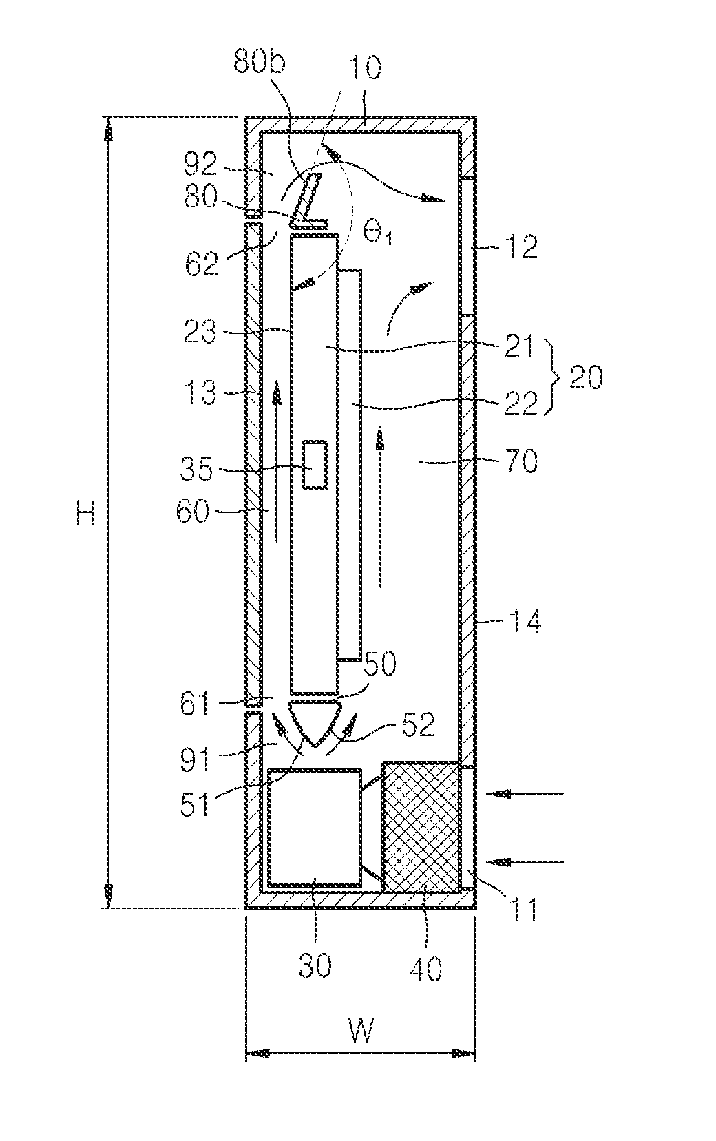
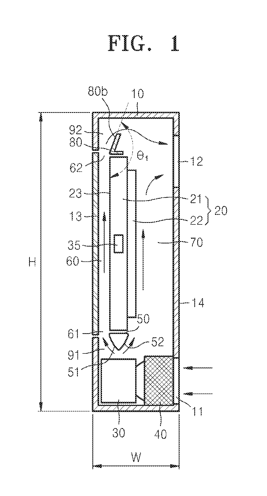
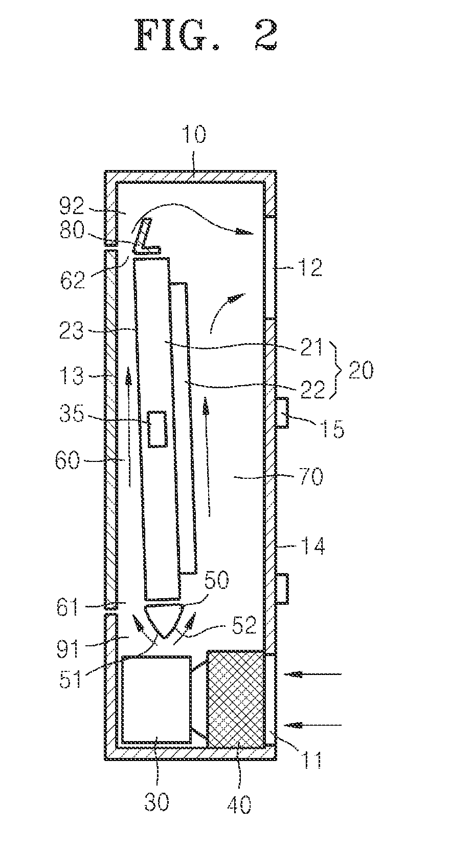
case 10
The case 10 can include a transparent window 13. A display surface 23 of the display unit 20 can face the transparent window 13, such that an image generated and displayed on panel 21 is seen by a user through the transparent window 13. The transparent window 13 and the display surface 23 are spaced apart from each other to form a first air flow path 60 to cool the front of the display unit 20. A diffuser 80 can be installed at an exit 62 of the first air flow path 60. A light source device such as a backlight unit (not illustrated) and the driving circuit unit 22 can be installed at the rear of the display unit 20. A second air flow path 70 can serve to cool the rear of the display unit 20 and is defined by a rear cover 14 of the case 10 and the rear of the display unit 20.
As illustrated in FIG. 1, the case 10 has a height H and a width W.
The ventilator 30 can intake air through an intake port 11 and then supply the admitted air to the first and second air flow paths 60 and 70. A f...
PUM
 Abstract
Description
Claims
Application Information
 - R&D
- Intellectual Property
- Life Sciences
- Materials
- Tech Scout
- Unparalleled Data Quality
- Higher Quality Content
- 60% Fewer Hallucinations
Browse by: Latest US Patents, China's latest patents, Technical Efficacy Thesaurus, Application Domain, Technology Topic, Popular Technical Reports.
© 2025 PatSnap. All rights reserved.Legal|Privacy policy|Modern Slavery Act Transparency Statement|Sitemap|About US| Contact US: help@patsnap.com