
Battery And Ultracapacitor Device And Method of Use

a battery and ultracapacitor technology, applied in the direction of capacitor propulsion, dynamo-electric converter control, cell components, etc., can solve the problems of increasing weight, increasing cost, and requiring multiple control devices, so as to reduce the number of control devices, occupy space on the vehicle, and reduce the effect of weigh

Inactive Publication Date: 2011-07-07
FORD GLOBAL TECH LLC
View PDF16 Cites 25 Cited by
  • Summary
  • Abstract
  • Description
  • Claims
  • Application Information

AI Technical Summary

Benefits of technology

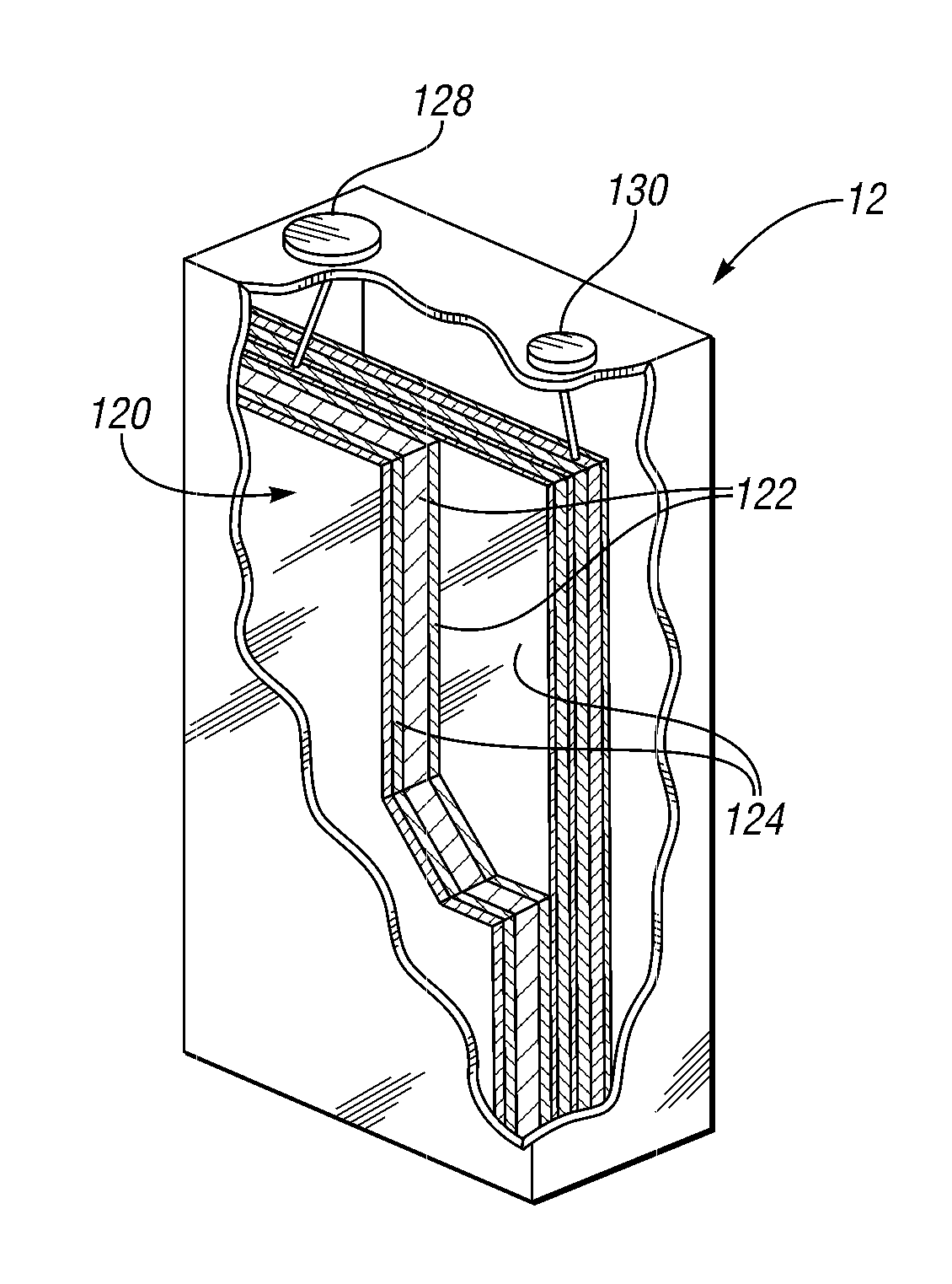
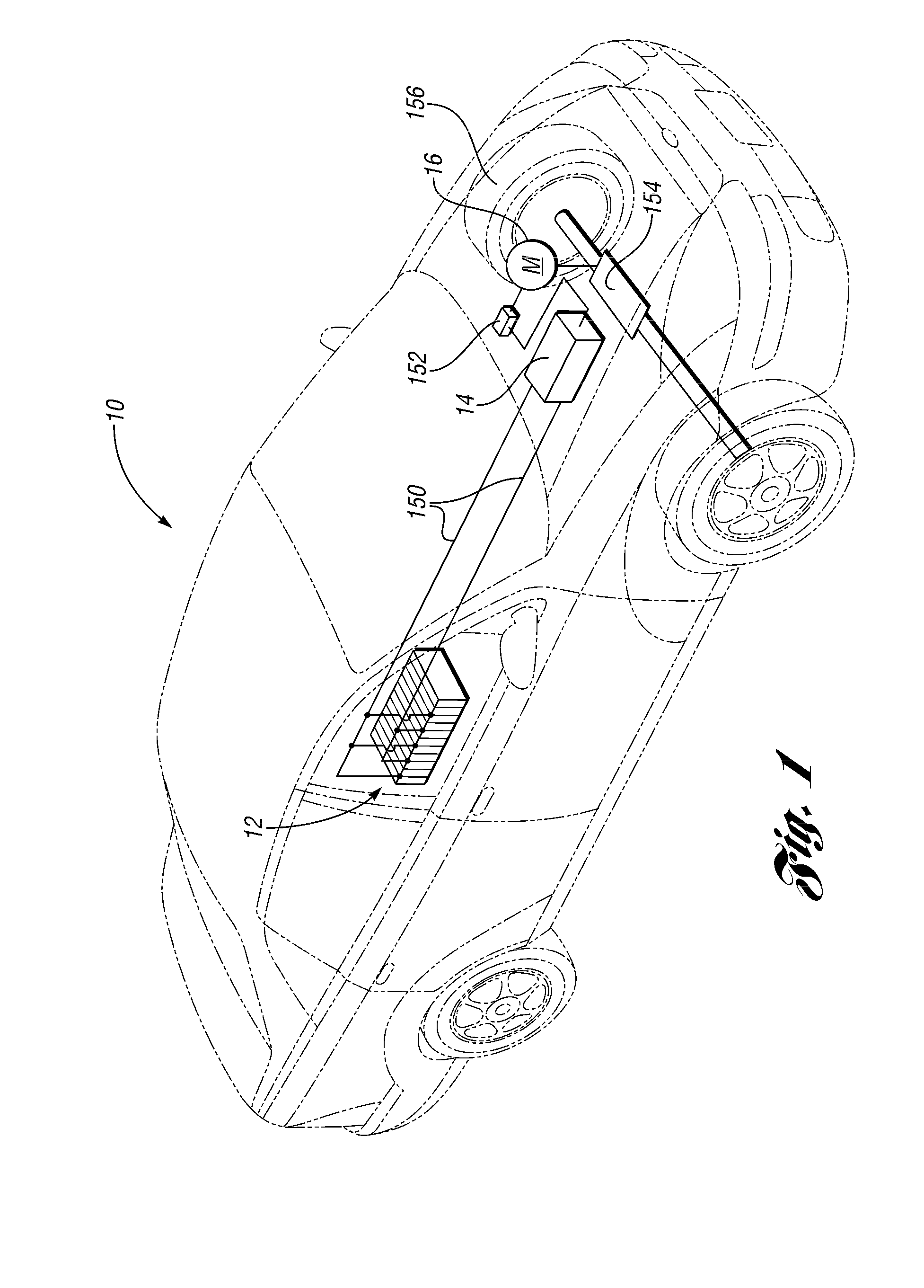
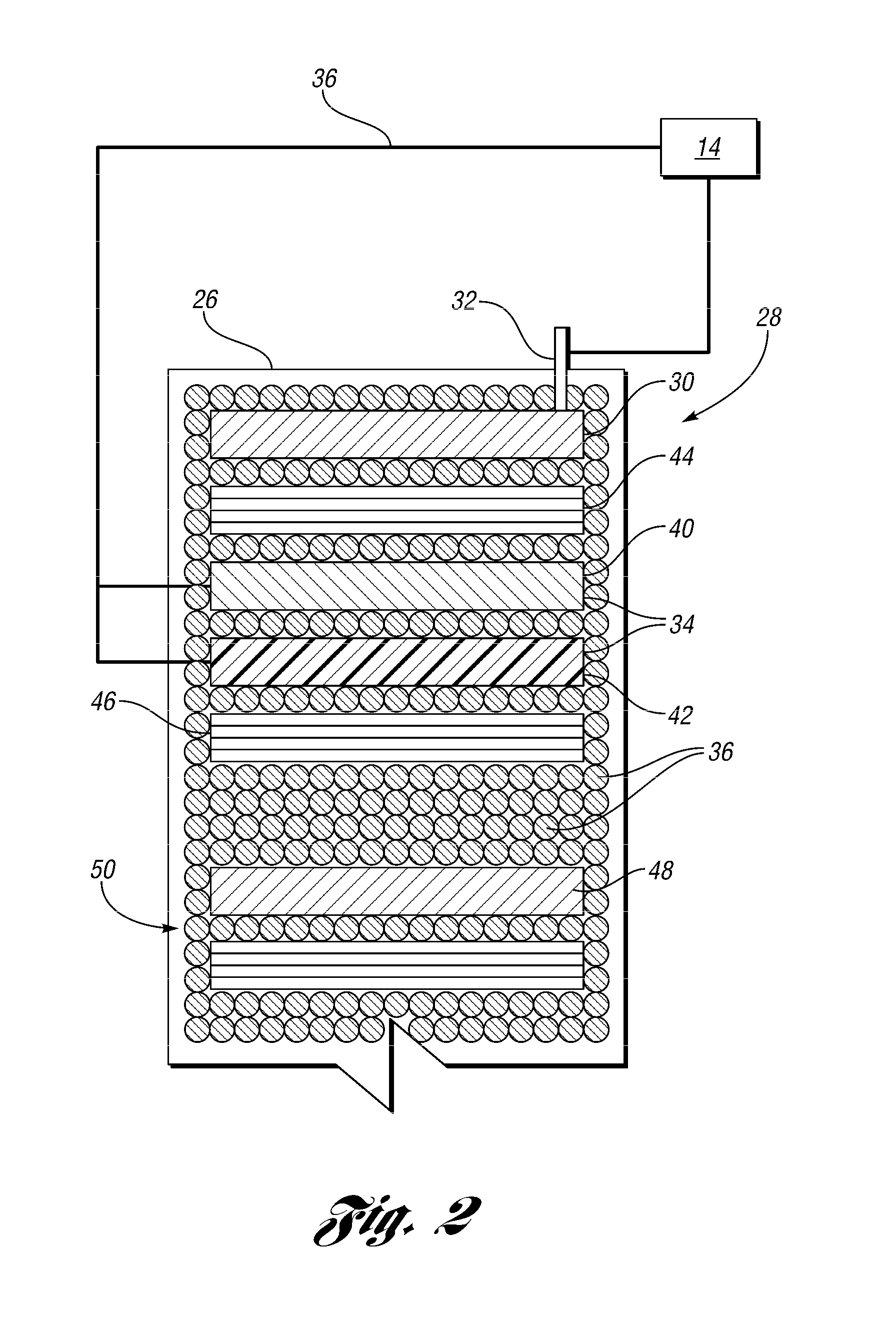
[0006]According to at least one embodiment disclosed herein, a battery and ultracapacitor device for use in a vehicle reduces the number of control devices that add weight and occupy space on a vehicle. The device includes a battery and ultracapacitor cell having a positive electrode, a first negative electrode, a second negative electrode, a first separator, and a controller. The first negative electrode has a first composition and communicates with the positive electrode. The second negative electrode has a second composition and is adjacent to the first negative electrode. The second negative electrode is also adjacent to a second separator. A second negative electrode communicates with the positive electrode and the first negative electrode. The first separator is disposed between the positive electrode and the first and second negative electrodes. The controller communicates with the positive electrode, the first negative electrode, and the second negative electrode. The first negative electrode comprises a secondary battery negative electrode and the second negative electrode comprises an ultracapacitor negative electrode.

Problems solved by technology

Using at least two sources of energy to power the HEVs requires multiple control devices that add weight, and additional cost.

Method used


Image

  • Battery And Ultracapacitor Device And Method of Use
  • Battery And Ultracapacitor Device And Method of Use
  • Battery And Ultracapacitor Device And Method of Use

Examples


Embodiment Construction

[0017]Reference will now be made in detail to compositions, embodiments and methods set forth herein, which include the best mode of practicing the invention presently known to the inventors. But, it should be understood that the disclosed embodiments are merely exemplary of the invention that may be embodied in various and alternative forms. Therefore, specific details disclosed herein are not to be interpreted as limiting, but merely as a representative basis for any aspect of the invention and / or as a representative basis for teaching one skilled in the art to variously employ the present invention.

[0018]Except in the operating examples, or where otherwise expressly indicated, all numbers in this description indicating material amounts, reaction conditions, or uses are to be understood as modified by the word “about” in describing the invention's broadest scope. Practice within the numerical limits stated is generally preferred. Also, unless expressly stated to the contrary:

[0019...


PUM

PropertyMeasurementUnit
thicknessesaaaaaaaaaa
internal resistanceaaaaaaaaaa
currentaaaaaaaaaa

Abstract

A battery and ultracapacitor device for use in a vehicle includes a positive electrode, a first negative electrode, a second negative electrode, a first separator disposed between the positive electrode and the first and second negative electrodes, and a controller communicating with the positive electrode, the first negative electrode, and the second negative electrode. A first negative electrode has a first composition and communicates with the first positive electrode. The second negative electrode has a second composition and is adjacent to the first negative electrode and a second separator. The second negative electrode communicates with the positive electrode and the first negative electrode. The first negative electrode comprises a secondary battery negative electrode. The second negative electrode comprises an ultracapacitor negative electrode.

Description

BACKGROUND[0001]1. Technical Field[0002]This disclosure relates to a battery and ultracapacitor device at the single cell level and the method of use.[0003]2. Background Art[0004]Some hybrid electric vehicles (HEVs) incorporate a high voltage battery device as a primary energy source and an ultracapacitor to provide high current pulses of a short duration. This device design provides excellent power and sufficient energy for powering HEVs.[0005]Using at least two sources of energy to power the HEVs requires multiple control devices that add weight, and additional cost.SUMMARY[0006]According to at least one embodiment disclosed herein, a battery and ultracapacitor device for use in a vehicle reduces the number of control devices that add weight and occupy space on a vehicle. The device includes a battery and ultracapacitor cell having a positive electrode, a first negative electrode, a second negative electrode, a first separator, and a controller. The first negative electrode has a ...

Claims


Application Information

Patent Timeline
Patent Type & Authority Applications(United States)
IPC IPC(8): H02P7/00H01M14/00H01M50/409H01M50/489
CPCB60L11/005H01M2/16H01M4/383H01M12/005Y02E60/13Y02T90/16H01G11/04H01G11/30H01G11/58Y02T10/7022B60L50/40Y02T10/70Y02E60/10H01M50/409H01G11/32H01M50/489
Inventor ELDER, RONALD CARLYANG, XIAO GUANGLEONARDI, FRANCO
Owner FORD GLOBAL TECH LLC
Learn More