
Display drive circuit

a technology of driving circuit and display, applied in the field of display driving circuit, can solve the problems of flicker phenomenon, large current consumption, and relatively high current consumption, and achieve the effect of reducing current consumption

Active Publication Date: 2011-07-07
SILICON WORKS CO LTD
View PDF4 Cites 24 Cited by
  • Summary
  • Abstract
  • Description
  • Claims
  • Application Information

AI Technical Summary

Benefits of technology

[0023]Accordingly, the present invention has been made in an effort to solve the problems occurring in the related art, and an object of the present invention is to provide a display driving circuit which can minimize current consumption.

Problems solved by technology

Also, a flicker phenomenon can occur due to the parasitic capacitance of TFTs (thin film transistors) disposed in a display panel.
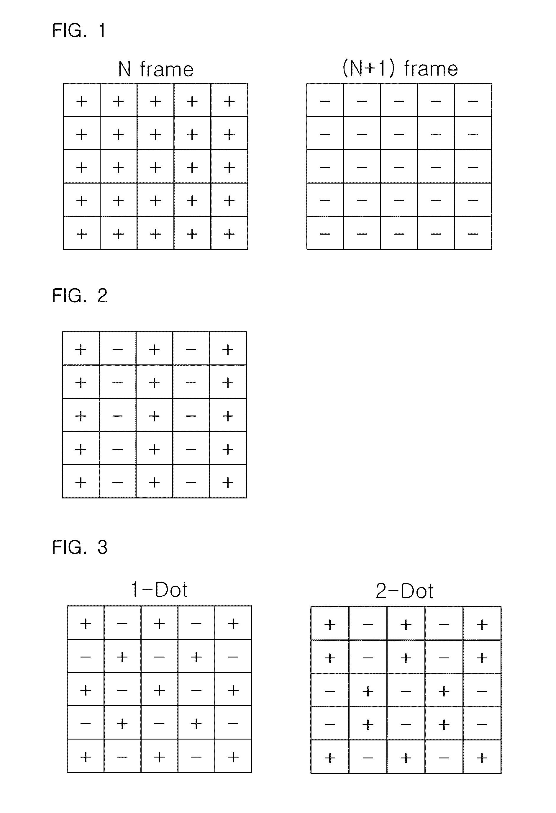
However, in the line inversion method, since the frequency of alternate current increases compared to the frame inversion method, disadvantages are caused in that current consumption relatively increases.
The dot inversion method shown in FIG. 3 can reduce the flicker phenomenon by using the spatial averaging technique, whereas it has disadvantages in that current consumption is most large since the frequency of alternate current is greater than the two above-described methods.
Nonetheless, in the charge sharing interval in which the charge sharing control signal SW3 is enabled, the transition from the first polarity (+) to the middle voltage level CSM and the transition from the second polarity (−) to the middle voltage level CSM require a substantial amount of current consumption, by which a drawback is caused.

Method used


Image

  • Display drive circuit
  • Display drive circuit
  • Display drive circuit

Examples


Embodiment Construction

[0037]Reference will now be made in greater detail to a preferred embodiment of the invention, an example of which is illustrated in the accompanying drawings. Wherever possible, the same reference numerals will be used throughout the drawings and the description to refer to the same or like parts.

[0038]FIG. 6 is a graph showing the waveforms of output terminals depending upon the turn-on resistance value of a charge sharing switch circuit in a charge sharing interval.

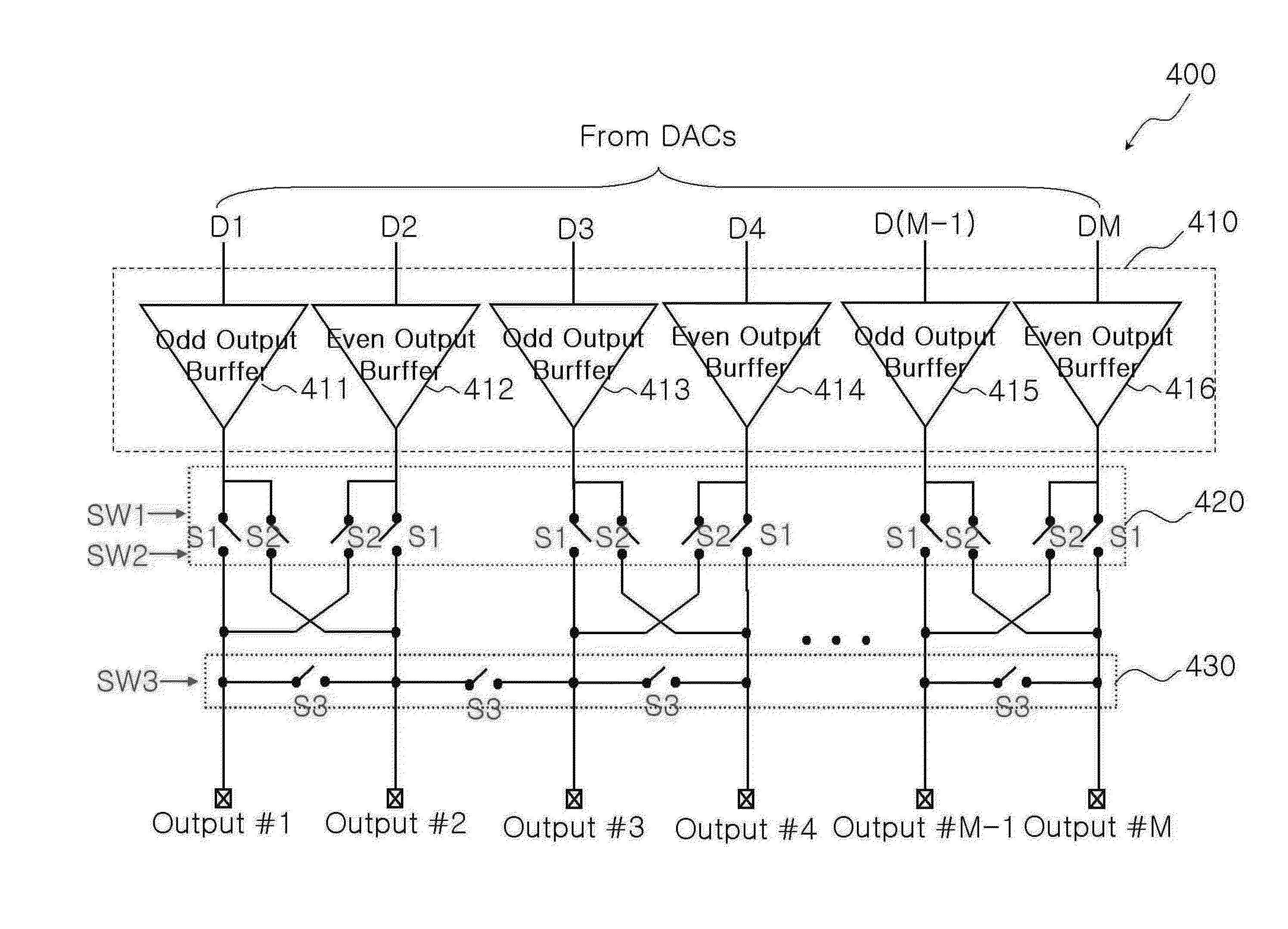
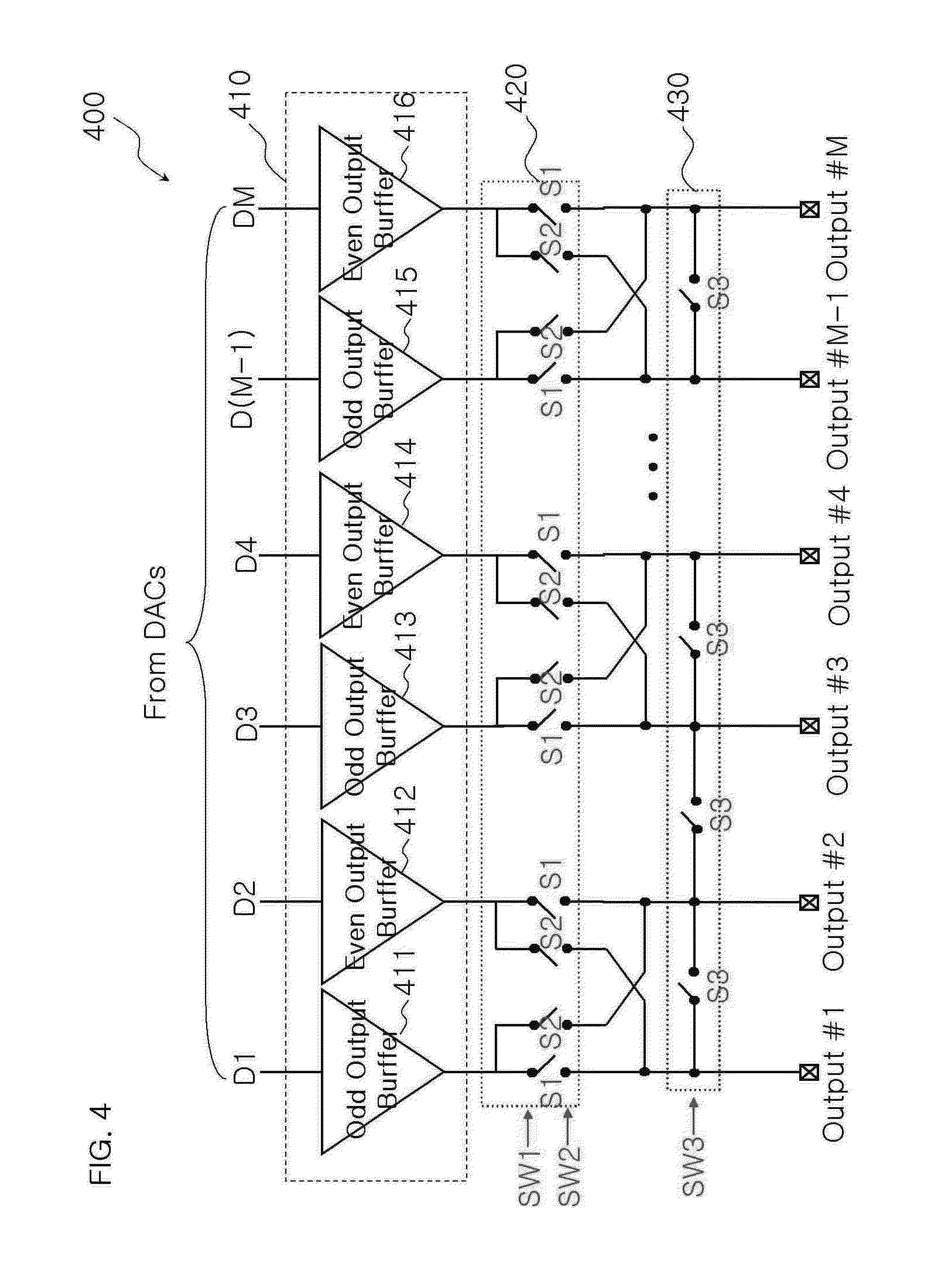
[0039]FIG. 6 depicts the waveforms of output signals in a valid data interval and a charge sharing interval, depending upon the turn-on resistance value Ron of the switches constituting the charge sharing switch circuit 430 shown in FIG. 4. Here, valid data means image data used for constituting a picture on a display panel, and the valid data interval means an interval during which the image data are transmitted to the display panel.

[0040]For the sake of convenience in explanation, the following description will be gi...


PUM


Abstract

A display driving circuit includes a buffer section, an N-dot switch circuit, a charge sharing switch circuit, and a sharing voltage level control switch circuit. The buffer section buffers a plurality of pixel driving signals outputted from a plurality of DACs. The N-dot switch circuit selects paths of the plurality of pixel driving signals outputted from the buffer section in response to a first path selecting signal or a second path selecting signal that is determined depending upon a dot inversion method, and switches the paths to a plurality of output terminals. The charge sharing switch circuit shares charges among the plurality of output terminals in response to a charge sharing control signal. The sharing voltage level control switch circuit controls charge sharing between the plurality of output terminals and a voltage level upon charge sharing, in response to a sharing voltage level control signal.

Description

BACKGROUND OF THE INVENTION[0001]1. Field of the Invention[0002]The present invention relates to a display driving circuit, and more particularly, to a display driving circuit which can reduce power consumption.[0003]2. Description of the Related Art[0004]In general, a display driving IC adopts an alternate current driving scheme in order to prevent an image sticking phenomenon that can occur due to the fact that various ionic or polar substances present in a display adhere to electrodes. Also, a flicker phenomenon can occur due to the parasitic capacitance of TFTs (thin film transistors) disposed in a display panel. Thus, in order to control the flicker phenomenon, an inversion driving method has been proposed in the art.[0005]The inversion driving method is generally divided into frame inversion, line inversion and dot inversion methods.[0006]FIG. 1 is a view explaining a frame inversion method.[0007]FIG. 2 is a view explaining a line inversion method.[0008]FIG. 3 is a view explai...

Claims


Application Information

Patent Timeline
Patent Type & Authority Applications(United States)
IPC IPC(8): G09G5/00
CPCG09G3/3614G09G3/3688G09G2330/021G09G2310/0297G09G2310/0248G09G3/36G09G3/20G02F1/133
Inventor SON, YOUNG-SUKSONG, HYUN-MINCHO, HYUN-JAAHN, YONG-SUNGOH, HYUNG-SEONGHAN, DAE-KEUN
Owner SILICON WORKS CO LTD
Learn More