
Focus detection apparatus, focus detection method, and image sensing apparatus

a focus detection and image technology, applied in the field of focus detection apparatus, focus detection method, image sensing apparatus, can solve the problems of inaccurate focus detection on the periphery, and the image cannot be restored according to the vignetting state of the luminous flux, so as to improve the focusing accuracy

Inactive Publication Date: 2011-07-07
CANON KK
View PDF6 Cites 22 Cited by
  • Summary
  • Abstract
  • Description
  • Claims
  • Application Information

AI Technical Summary

Benefits of technology

The present invention aims to improve focusing accuracy by restoring images according to the vignetting state of a luminous flux. This is achieved by providing a focus detection apparatus or method that includes image sensing means, storage means, calculation means, and focus state detection means. The apparatus or method detects the focus state of the imaging optical system based on the image signals generated by the calculations performed on the subject images obtained from the different pixel groups. The technical effect of this invention is to improve the accuracy of focusing in image capture devices.

Problems solved by technology

Thus, the inventions disclosed in Japanese Patent Laid-Open No. 58-24105, Japanese Patent No. 2959142, and Japanese Patent Laid-Open No. 2005-106994 have a problem in that accurate focus detection is not possible on peripheries of the photographic screen if correlation calculation is performed based on the image generated by the luminous flux passing through the area Sα on the pupil of the photographing lens and the image generated by the luminous flux passing through the area Sβ on the pupil of the photographing lens.
Also, the technique disclosed in Japanese Patent Laid-Open No. 5-127074 has the disadvantage that images cannot be restored according to vignetting state of the luminous flux even if the specific filter contained in the camera is deformed according to conditions.

Method used


Image

  • Focus detection apparatus, focus detection method, and image sensing apparatus
  • Focus detection apparatus, focus detection method, and image sensing apparatus
  • Focus detection apparatus, focus detection method, and image sensing apparatus

Examples


Embodiment Construction

Preferred embodiments of the present invention will be described in detail in accordance with the accompanying drawings. The dimensions, shapes and relative positions of the constituent parts shown in the embodiments should be changed as convenient depending on various conditions and on the structure of the apparatus adapted to the invention, and the invention is not limited to the embodiments described herein.

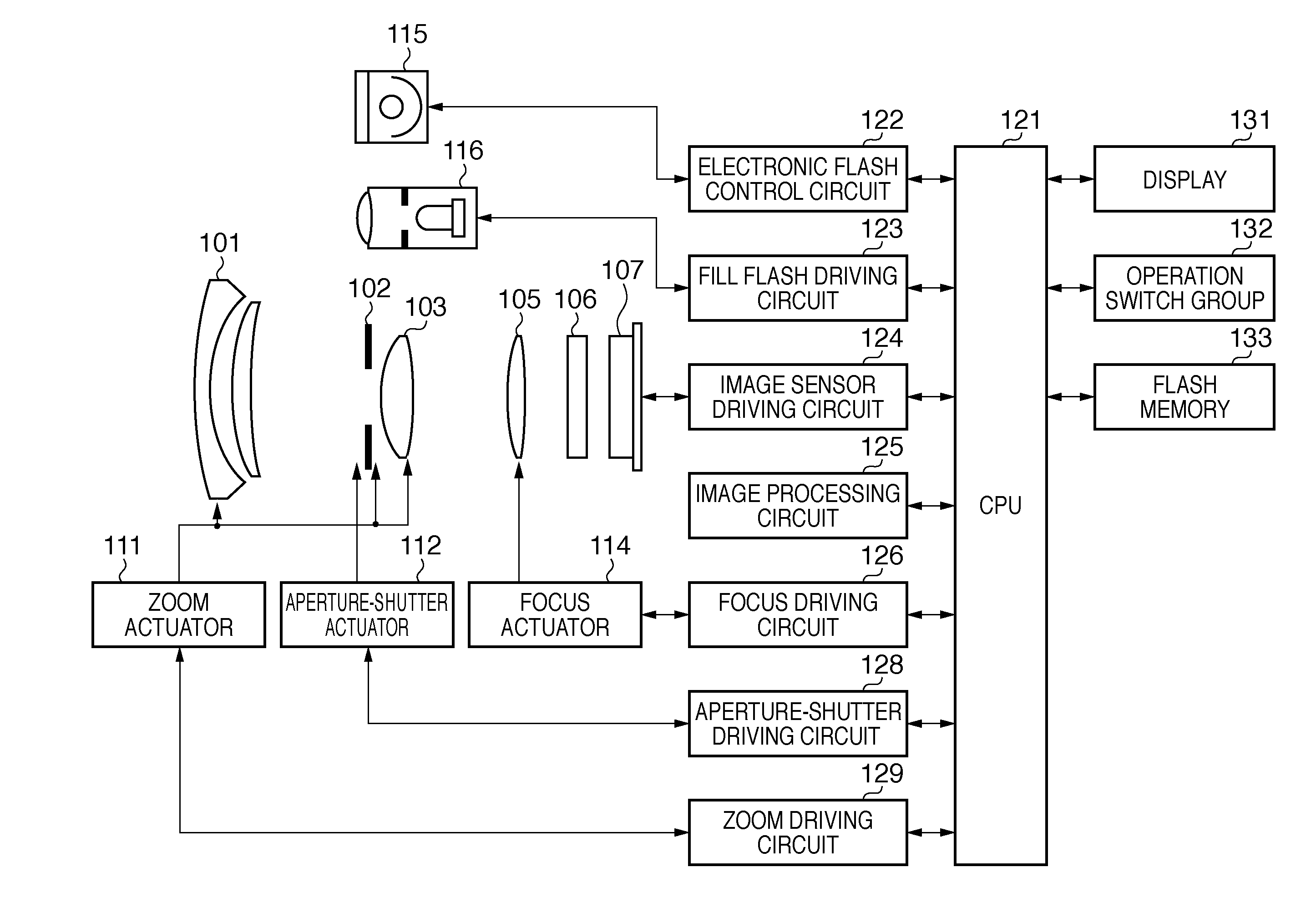
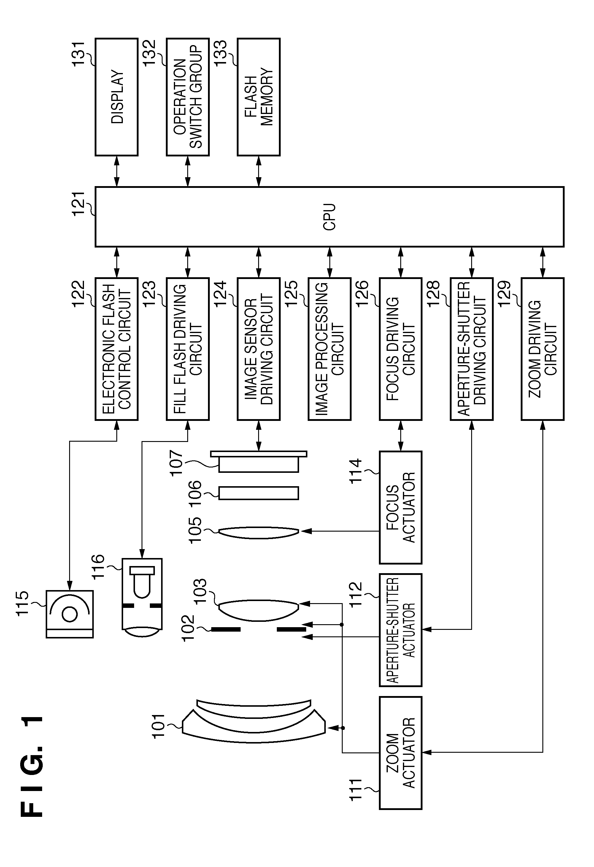
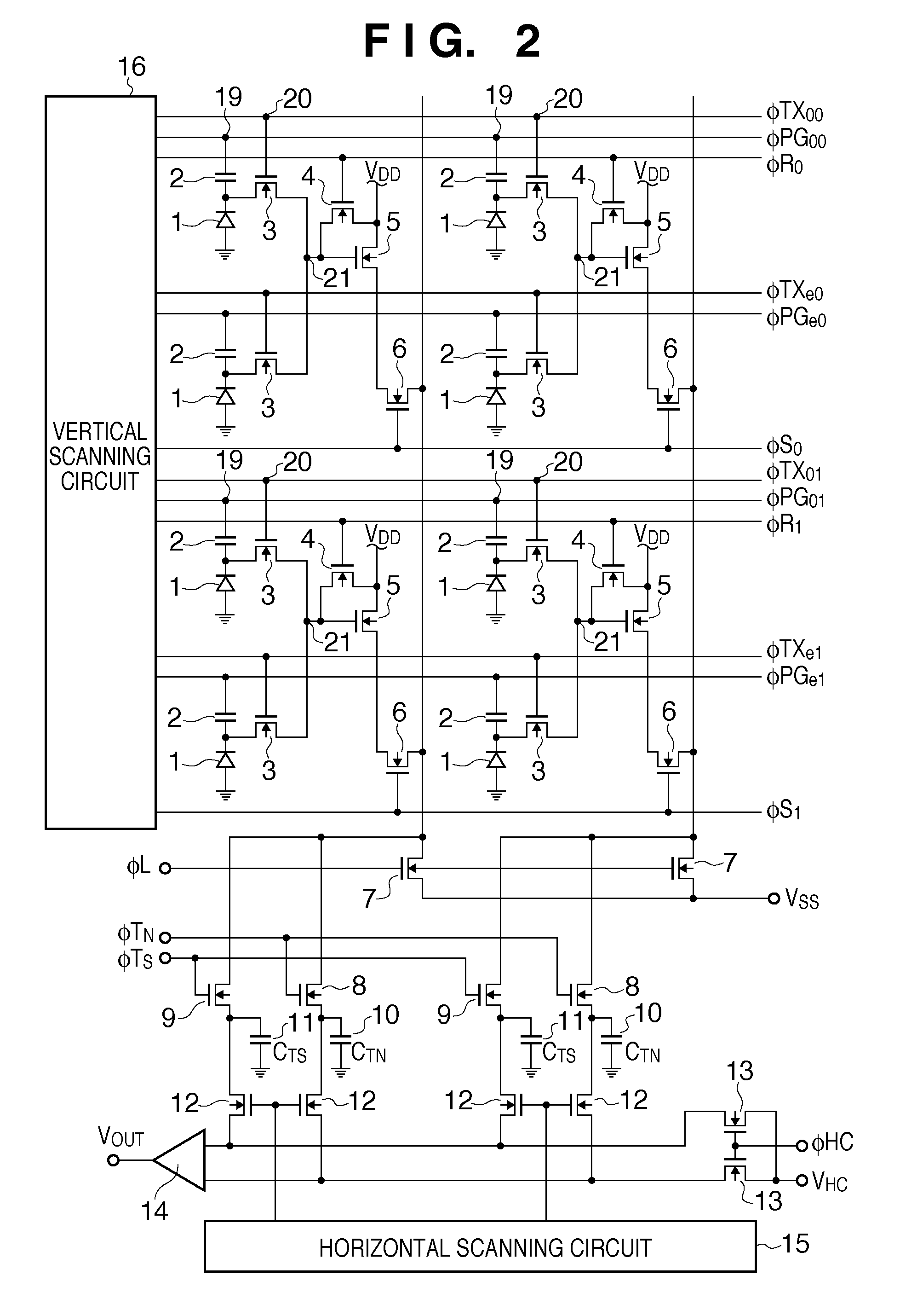
FIG. 1 is a block diagram of an image sensing apparatus according to a preferred embodiment of the present invention, showing an electronic camera made up of a camera body containing an image sensor, and a photographic optical system integral with the camera body. In FIG. 1, reference numeral 101 denotes a first lens group placed at the distal end of the photographic optical system (imaging optical system), being held in such a way as to be able to move forward and backward along an optical axis. Reference numeral 102 denotes an aperture-shutter which has capabilities to adjus...


PUM


Abstract

A focus detection apparatus includes an image sensor that has a first pixel group which receives a luminous flux passing a first pupil area of an imaging optical system, and a second pixel group which receives a luminous flux passing a second pupil area different from the first pupil area; a storage unit that stores first and second distribution functions corresponding to the first and second pupil areas, respectively; a calculation unit that generates a first image signal by performing calculations on a first subject image, obtained from the first pixel group, using the second distribution function, and generates a second image signal by performing calculations on a second subject image, obtained from the second pixel group, using the first distribution function; and a focus state detection unit that detects a focus state of the imaging optical system based on the first and the second image signals.

Description

TECHNICAL FIELDThe present invention relates to a focus detection apparatus, focus detection method, and image sensing apparatus, and more particularly, to a focus detection apparatus and focus detection method used in an image sensing apparatus, such as a digital still camera, capable of detecting an in-focus state of a photographing lens based on an image obtained from an image sensor for image sensing.BACKGROUND ARTRegarding systems for detecting an in-focus state of a photographing lens in a digital camera which photographs using an image sensor, an apparatus which performs pupil division-based focus detection using a two-dimensional sensor is disclosed in Japanese Patent Laid-Open No. 58-24105, where the two-dimensional sensor has a microlens formed in each pixel. In the apparatus disclosed in Japanese Patent Laid-Open No. 58-24105, a photoelectric converter in each pixel of the image sensor is divided into multiple parts and the divided photoelectric converter is configured to...

Claims


Application Information

Patent Timeline
Patent Type & Authority Applications(United States)
IPC IPC(8): H04N5/225H04N25/00
CPCG02B7/36G03B13/36H04N2101/00H04N5/3696H04N5/23212H04N23/672H04N23/675H04N25/704H04N25/134H04N25/77
Inventor HASHIMOTO, YOSHITAKANAGANO, AKIHIKO
Owner CANON KK
Learn More