Integrated wireless power system

a wireless power system and integrated technology, applied in the direction of transformers, inductances, instruments, etc., can solve the problems of difficult shielding to reduce interference effectively, difficult to effectively utilize shielding to reduce interference, and reduce the so as to reduce interference, reduce quality or ability of external communication, and reduce interference

Inactive Publication Date: 2011-07-07
ACCESS BUSINESS GRP INT LLC
View PDF99 Cites 65 Cited by
  • Summary
  • Abstract
  • Description
  • Claims
  • Application Information

AI Technical Summary

Benefits of technology

This patent describes a way to make electronic items like smartphones last longer when they are charged wirelessly. It works by creating a new kind of signal that helps to cancel out other signals that might interrupt the phone's battery. This technology can be added to things people already use everyday, such as coffee machines or radios, making them easier to recharge on-the go.

Problems solved by technology

The technical problem addressed in this patent is the limited compatibility between different portable devices and conventional integrated charging systems, which results in users having to purchase separate charging solutions for each device. Additionally, there is concern over potential interference caused by unsolicited signal injection during communication among these devices. Users who want to enjoy convenient integration within a larger ecosystem face difficulty in finding suitable charging options due to varying device configurations and power requirements.

Method used


Image

  • Integrated wireless power system
  • Integrated wireless power system
  • Integrated wireless power system

Examples


Embodiment Construction

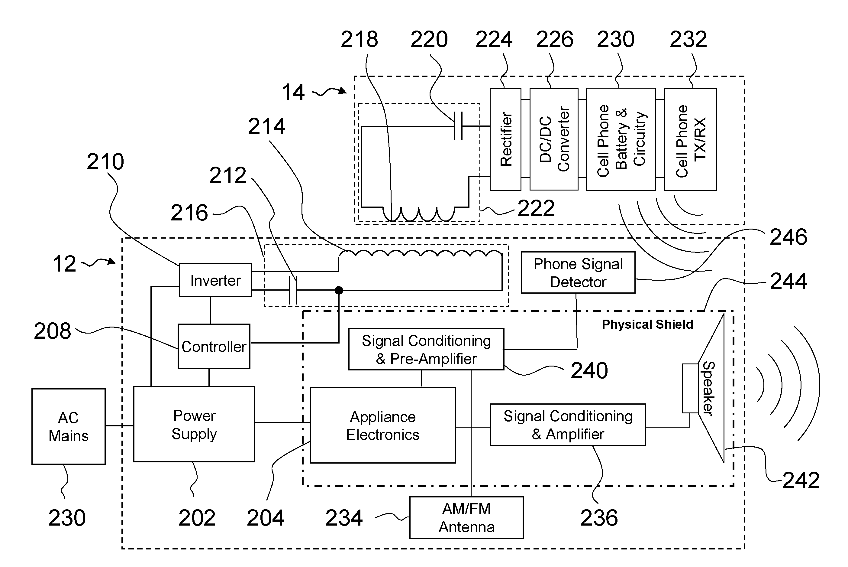
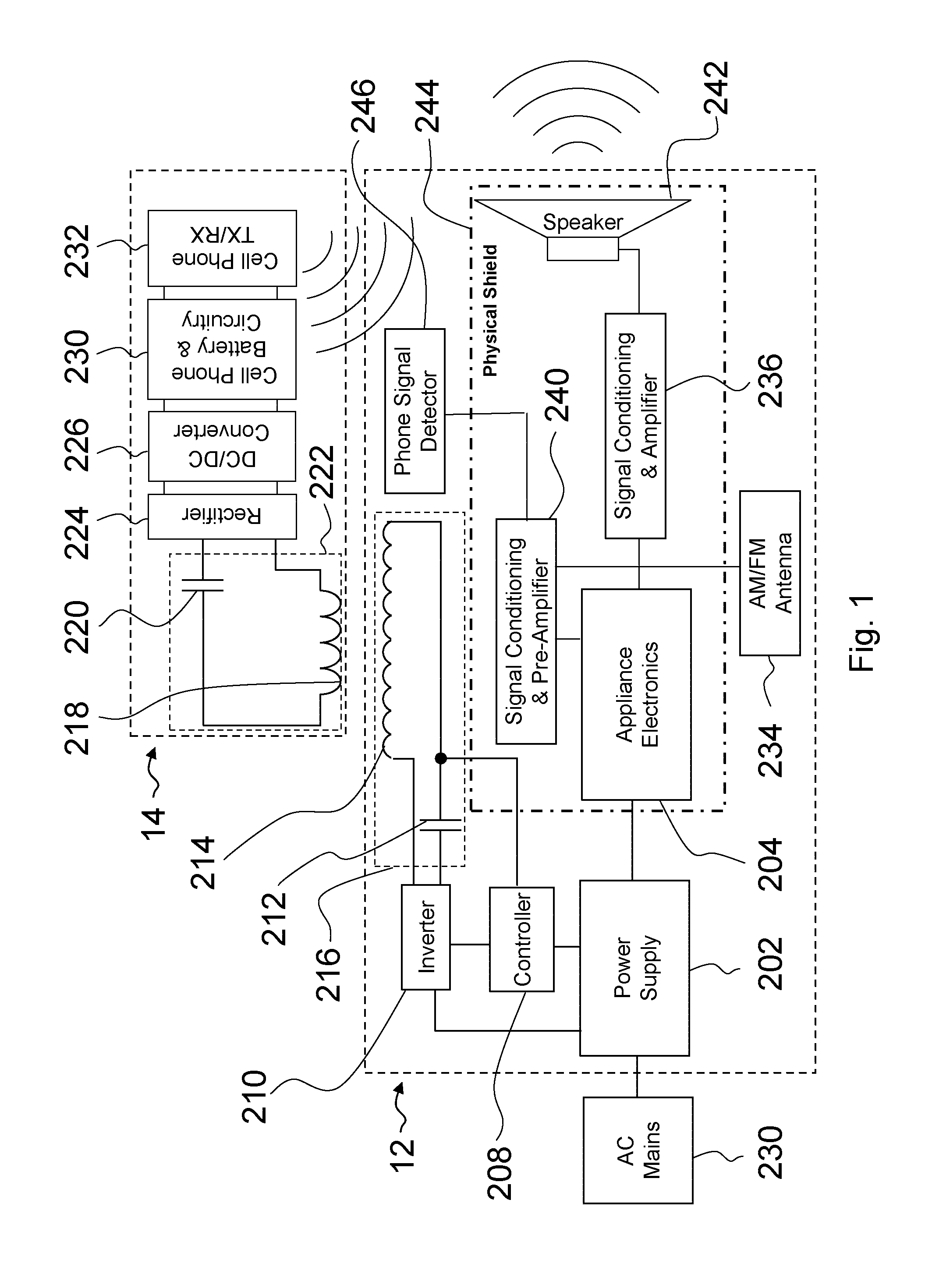
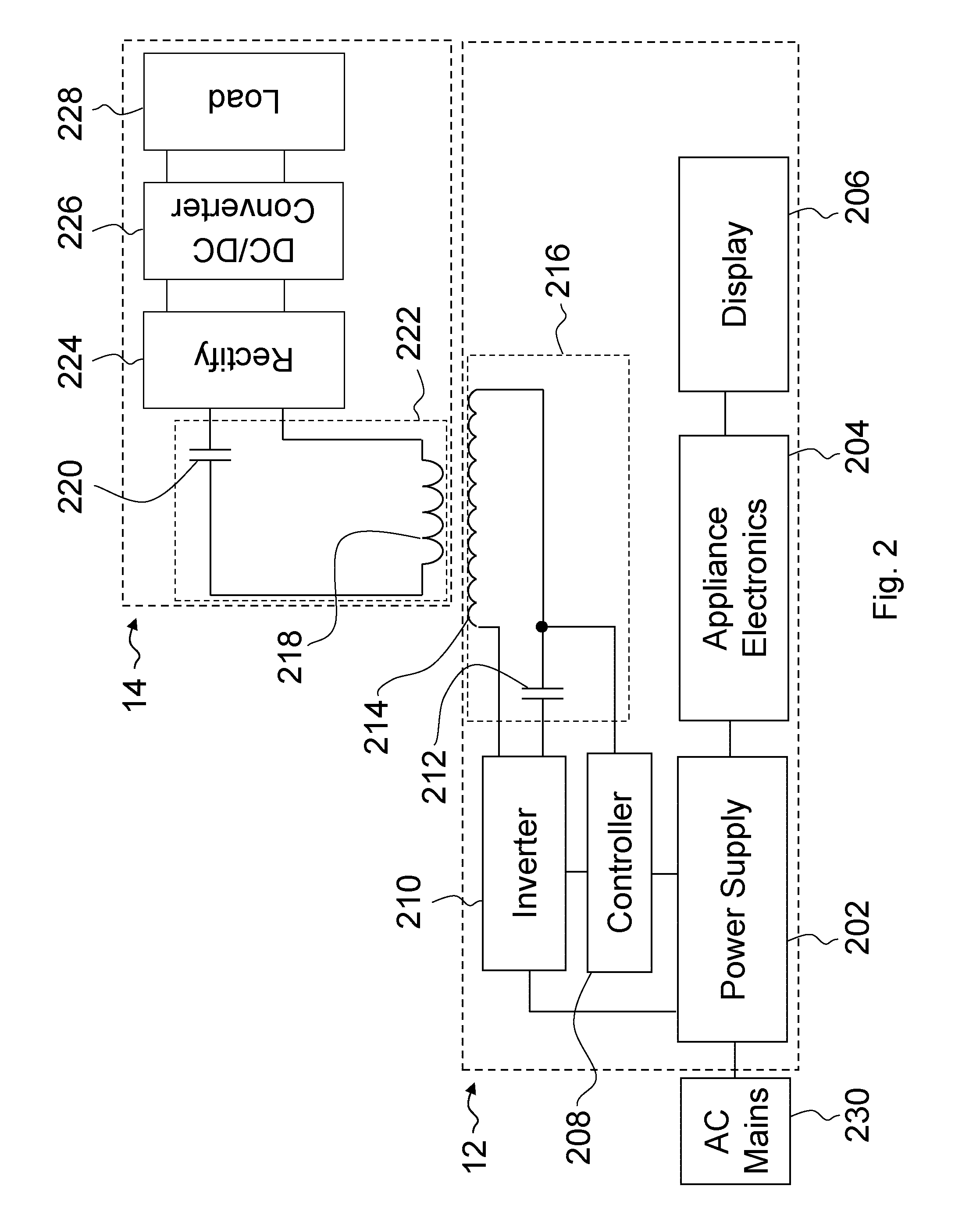
[0027]An integrated wireless power system in accordance with an embodiment of the present invention is shown in FIG. 1. The integrated wireless power system includes an integrated wireless power appliance 12 and a remote device 14 capable of receiving wireless power. The integrated wireless power system of FIG. 1 includes interference cancellation circuitry. FIG. 2 shows an alternative embodiment of an integrated wireless power system that is somewhat similar to the integrated wireless power system of FIG. 1, but does not include any interference cancellation circuitry.

[0028]In some embodiments, the integrated wireless power appliance 12 is specifically adapted for use in a residence. For example, the integrated wireless power appliance may be located within a residence such as a household, hotel, motel, bed and breakfast, dormitory. The residence may have multiple users over time, each with separate portable devices 14. The integrated wireless charging apparatus may include wireles...


PUM


Abstract

The present configuration provides an integrated wireless power system for powering or charging a portable device. The integrated wireless power system includes 1) an integrated wireless power appliance that both provides power as well as additional functionality, such as timekeeping, radio, and alarm functionality and 2) a portable device capable of receiving wireless power from the integrated wireless power appliance.

Description


Claims


Application Information

Patent Timeline
Owner ACCESS BUSINESS GRP INT LLC
Why Eureka
Try Eureka