
Tool head positioning structure for flexible wrench

Active Publication Date: 2011-07-14
INFAR IND CO LTD
View PDF6 Cites 8 Cited by
  • Summary
  • Abstract
  • Description
  • Claims
  • Application Information

AI Technical Summary

Benefits of technology

[0009]According to the present invention, the main purpose is to provide a tool head positioning structure for a flexible wrench; in which, a handle, which includes a controller, is pivotally connected to a tool head; a retaining member, which includes a pushing edge and a retracting portion, is slidably inserted between the controller and the tool head, in which, a depth of the pushing edge is different from that of the retracting portion; while the retaining member is respectively aligned with the pushing edge or the retracting portion, the retaining member can be engaged or released to the tool head so as to fix or adjust an angle of the tool head; a fillet portion, which is formed between the pushing edge and retracting portion, can provide a user to operate the flexible wrench smoothly.
[0010]A second purpose is to provide a tool head positioning structure for a flexible wrench; in which, the handle 10 further has a resilient device adjacent to the controller, and the controller further has a positioning structure corresponding to the resilient device; the controller can be elastically positioned due to the engagement of the resilient device and the positioning structure so that the fixing and the rotating of the tool head can be more precisely.
[0011]A third purpose is to provide a tool head positioning structure for a flexible wrench; in which, the controller includes a bar formed thereon for a user to operate the wrench easily.

Problems solved by technology

The traditional flexible wrench has a drawback of improper swing so that some people reform the flexible wrench to add a toothed-structure on a outer periphery of a pivotal section of the tool head, and an engaging structure on the handle corresponding to the toothed-structure.
However, the toothed-structure of the tool head may be skip even the engaging structure has engaged therewith.
Firstly, the structure is not stable: the retaining member 72 is disposed on the inclined surface 711 of the control bar 71, and the retaining member 72 will provide an unwanted transverse component of force to the control rod 71 while the retaining member 72 is borne a retracting force. The control rod 71 may be displaced by the unwanted transverse component of force so that the control rod 71 is difficult to keep the retaining member 72 to engage with the tool head.
Secondly, the structure is not convenient: an exposing direction of the control bar 71 is on a lateral side of the wrench, a user has to press the control bar 71 laterally to fix the angle of the tool head, in which, the operation step is different from the traditional methods, and that it is difficult to confirm the control bar 71 is fully compressed.

Method used


Image

  • Tool head positioning structure for flexible wrench
  • Tool head positioning structure for flexible wrench
  • Tool head positioning structure for flexible wrench

Examples


Embodiment Construction

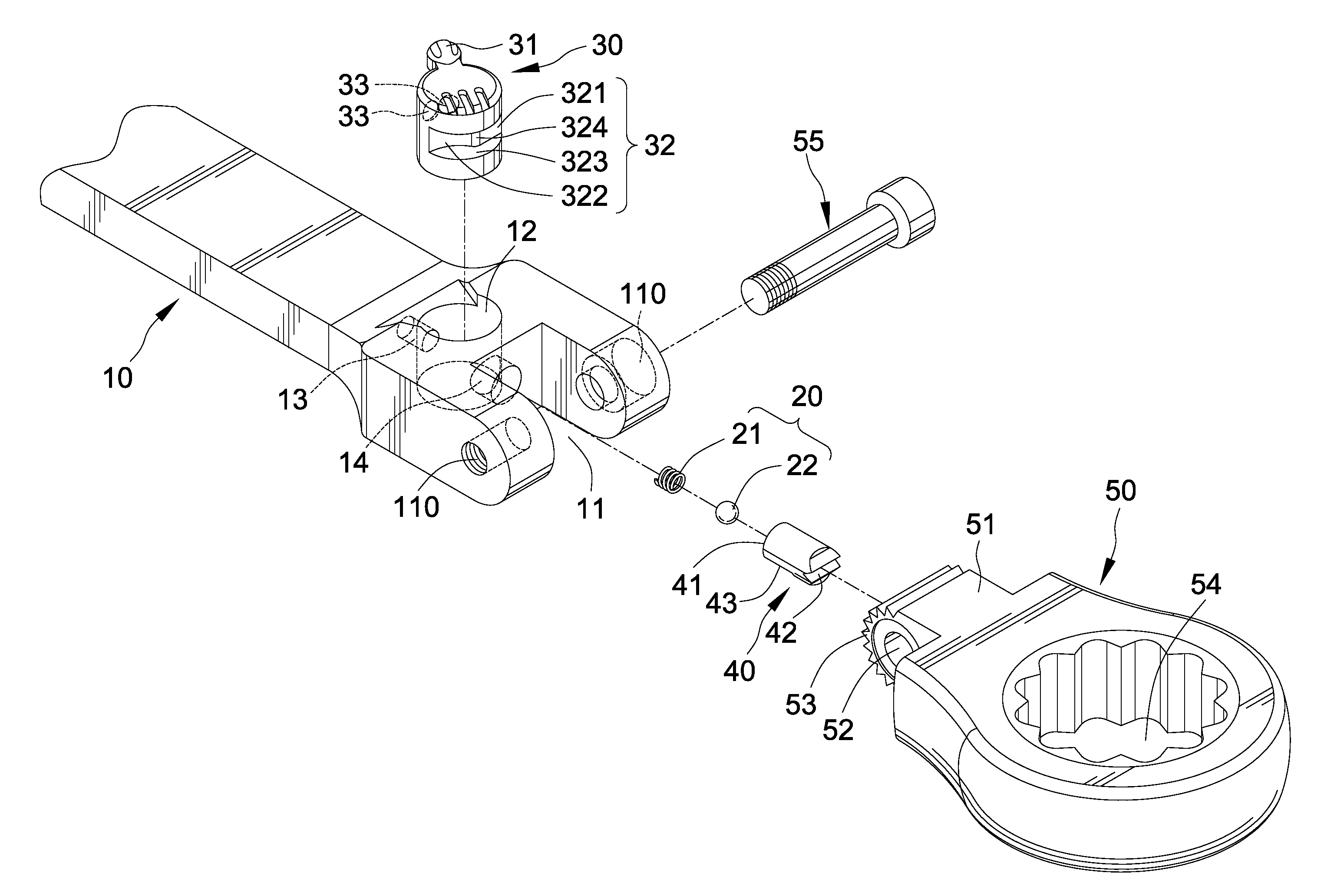
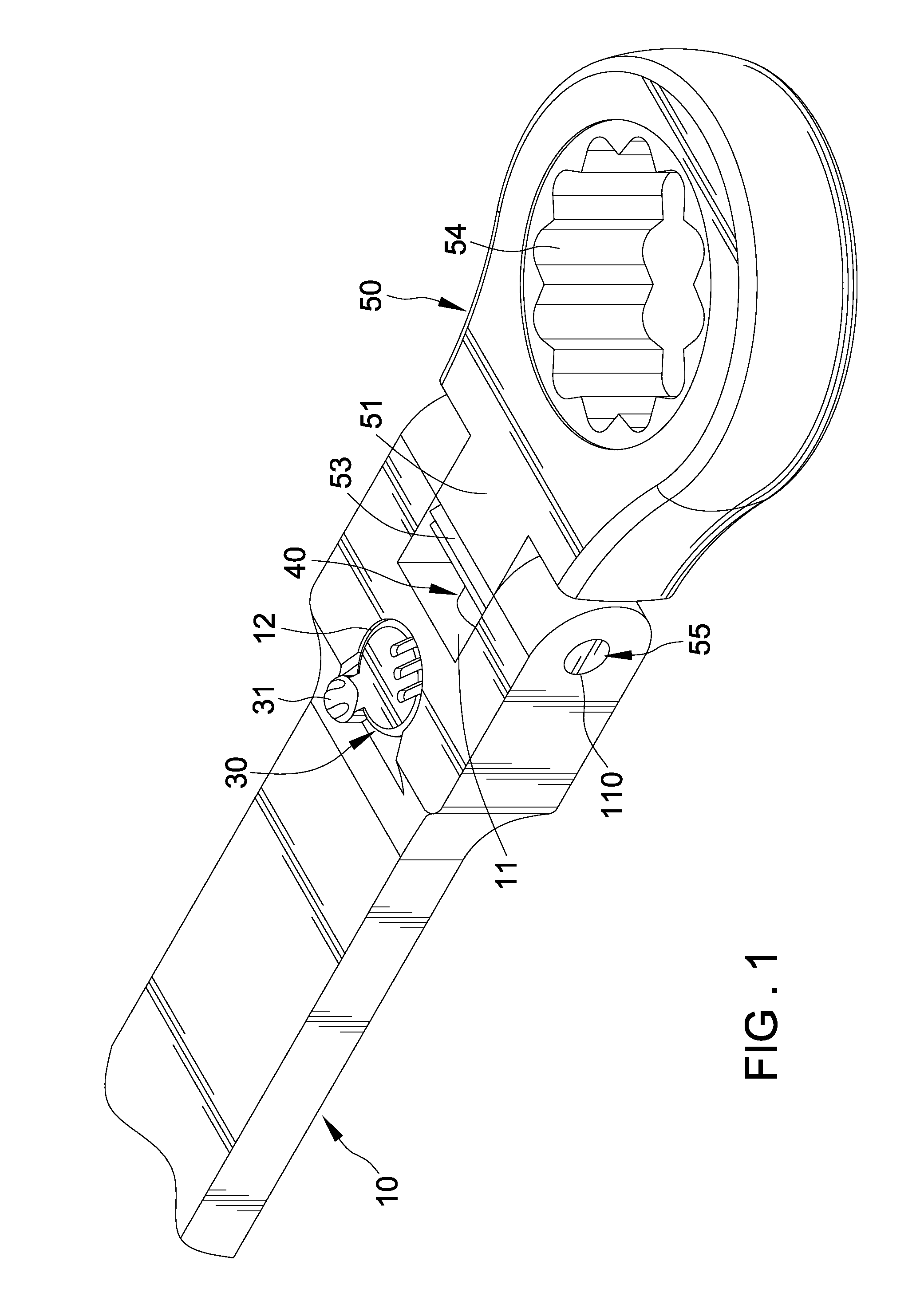
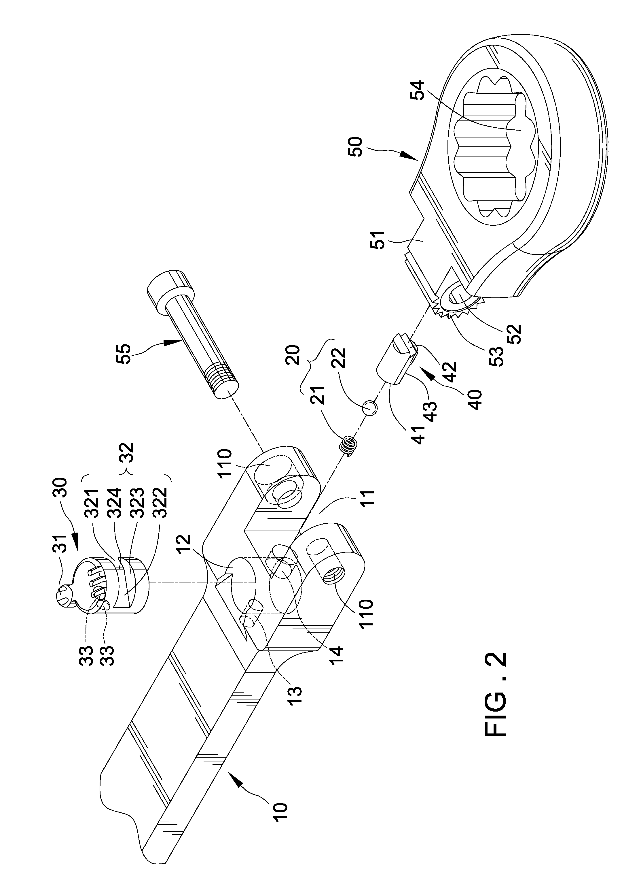
[0025]Referring to FIG. 1 through 3, a flexible wrench comprises a handle 10 defining a proximal end, and a tool head 50 defining a pivotal portion 51. The proximal end of the handle 10 and the pivotal portion 51 of the head 50 are connected with each other and define a pivotal axis. The pivotal portion 51 includes a channel 52 extending therethrough along the pivotal axis, and a retaining portion 53 formed thereon. The retaining portion 53 substantially surrounds a pivotal axis. Preferably, the retaining portion 53 has plurality of teeth. The tool head further includes a driving member 54 to be associated with a screw, nut or tool head.

[0026]The proximal end of the handle 10 forms a receptacle 11 corresponding to the pivotal portion 51 of the tool head 50. The receptacle 11 defines two lateral walls and a bottom disposed between the two lateral walls. Two holes 110 extend through the lateral walls respectively, and the holes 110 corresponds to the channel 52 of the pivotal portion ...


PUM


Abstract

According to the present invention, the main purpose is to provide a tool head positioning structure for a flexible wrench, which includes a handle and a tool head pivotally connected to the handle. The handle includes a controller associated with a retaining member disposed between the controller and the tool head, and the retaining member can be controlled to approach or away from the tool head by rotating the controller. The controller has two continued surfaces, which are pushing portion and retracting portion respectively, and each surface has a depth different from each other. The handle further includes a resilient device engaged to the controller so as to keep in a required position. A user can rotate the controller to make the pushing portion or the retracting portion be aligned with the retaining member so as to fix or adjust an angle of the tool head.

Description

BACKGROUND OF THE INVENTION[0001]1. Field of the Invention[0002]The present invention relates to a tool head positioning structure for a flexible wrench and, more particularly, to a flexible wrench whose tool head can be fixed in a required angle.[0003]2. Description of the Related Art[0004]A traditional flexible wrench is formed with a handle pivotally connected to a tool head without any tool head positioning structure such that the tool head can not be positioned precisely while operating the wrench. The traditional flexible wrench has a drawback of improper swing so that some people reform the flexible wrench to add a toothed-structure on a outer periphery of a pivotal section of the tool head, and an engaging structure on the handle corresponding to the toothed-structure. The engaging structure comprises a detent ball and a resilient member abutted against the detent ball. However, the toothed-structure of the tool head may be skip even the engaging structure has engaged therew...

Claims


Application Information

Patent Timeline
IPC IPC(8): B25B23/16
CPCB25G1/063B25B23/0028
Inventor CHEN, TAI-HUNG
Owner INFAR IND CO LTD
Features
  • Generate Ideas
  • Intellectual Property
  • Life Sciences
  • Materials
  • Tech Scout
  • Unparalleled Data Quality
  • Higher Quality Content
  • 60% Fewer Hallucinations
Learn More