Reservoir filling device

Inactive Publication Date: 2011-07-14
UNOMEDICAL AS
View PDF62 Cites 27 Cited by
  • Summary
  • Abstract
  • Description
  • Claims
  • Application Information

AI Technical Summary

Problems solved by technology

A problem which arises when manufacturing such filling devices is how to place the venting channel in order not t

Method used


Image

  • Reservoir filling device
  • Reservoir filling device
  • Reservoir filling device

Examples


Embodiment Construction

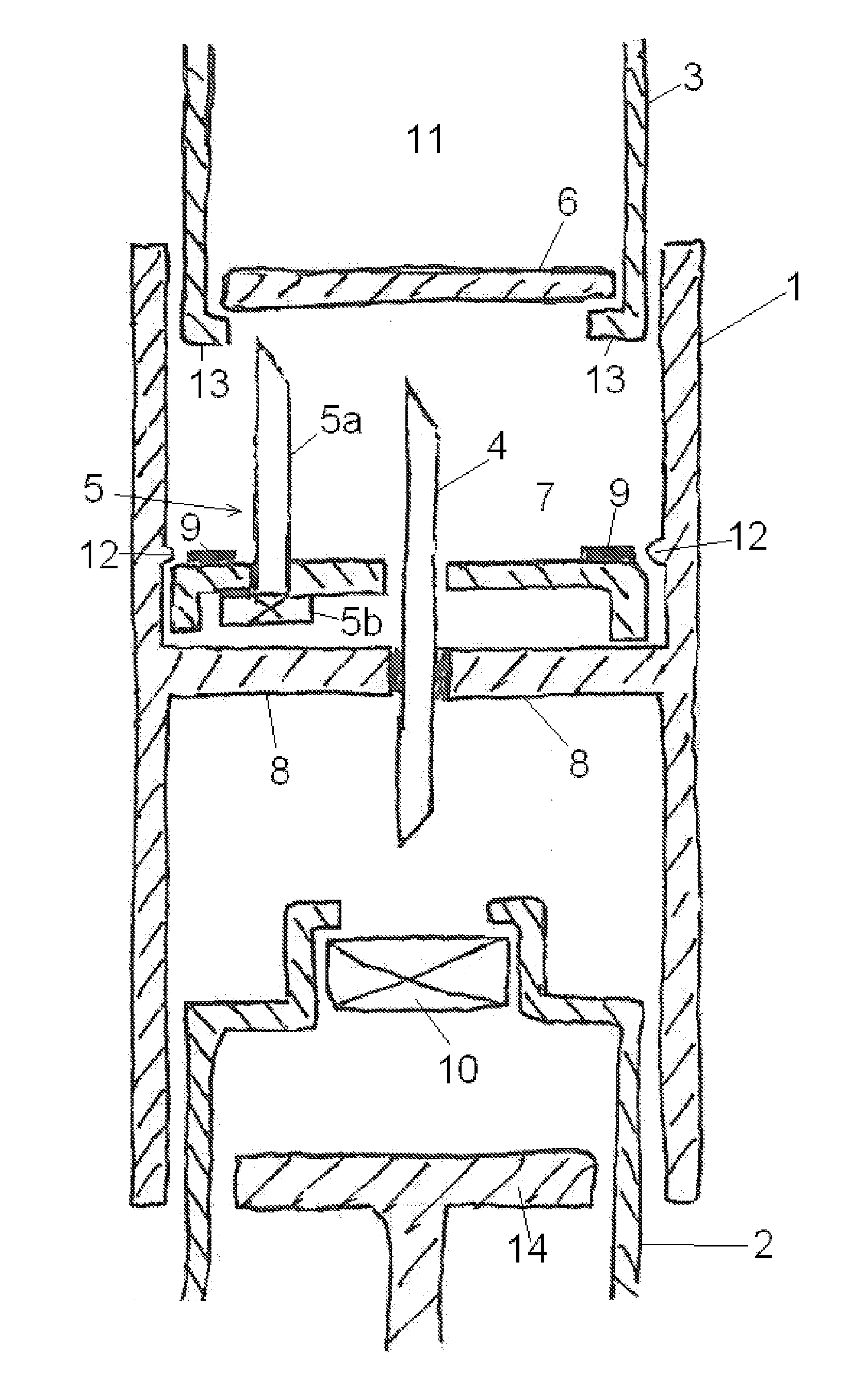
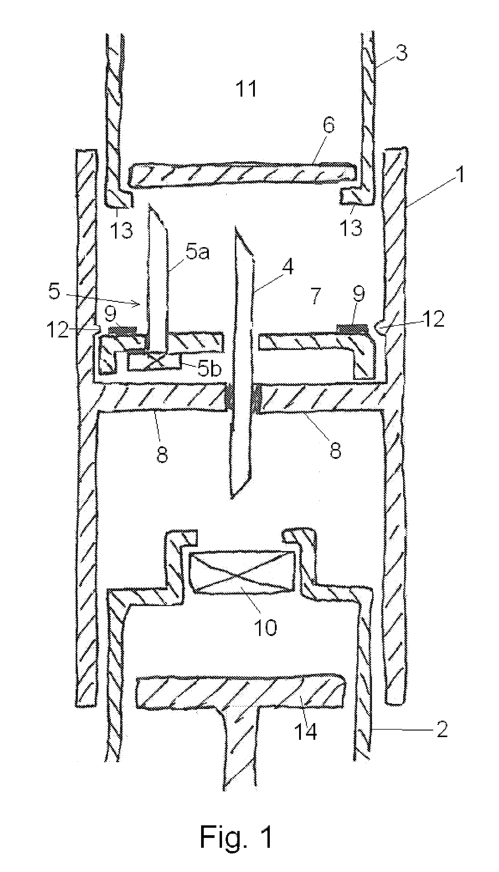
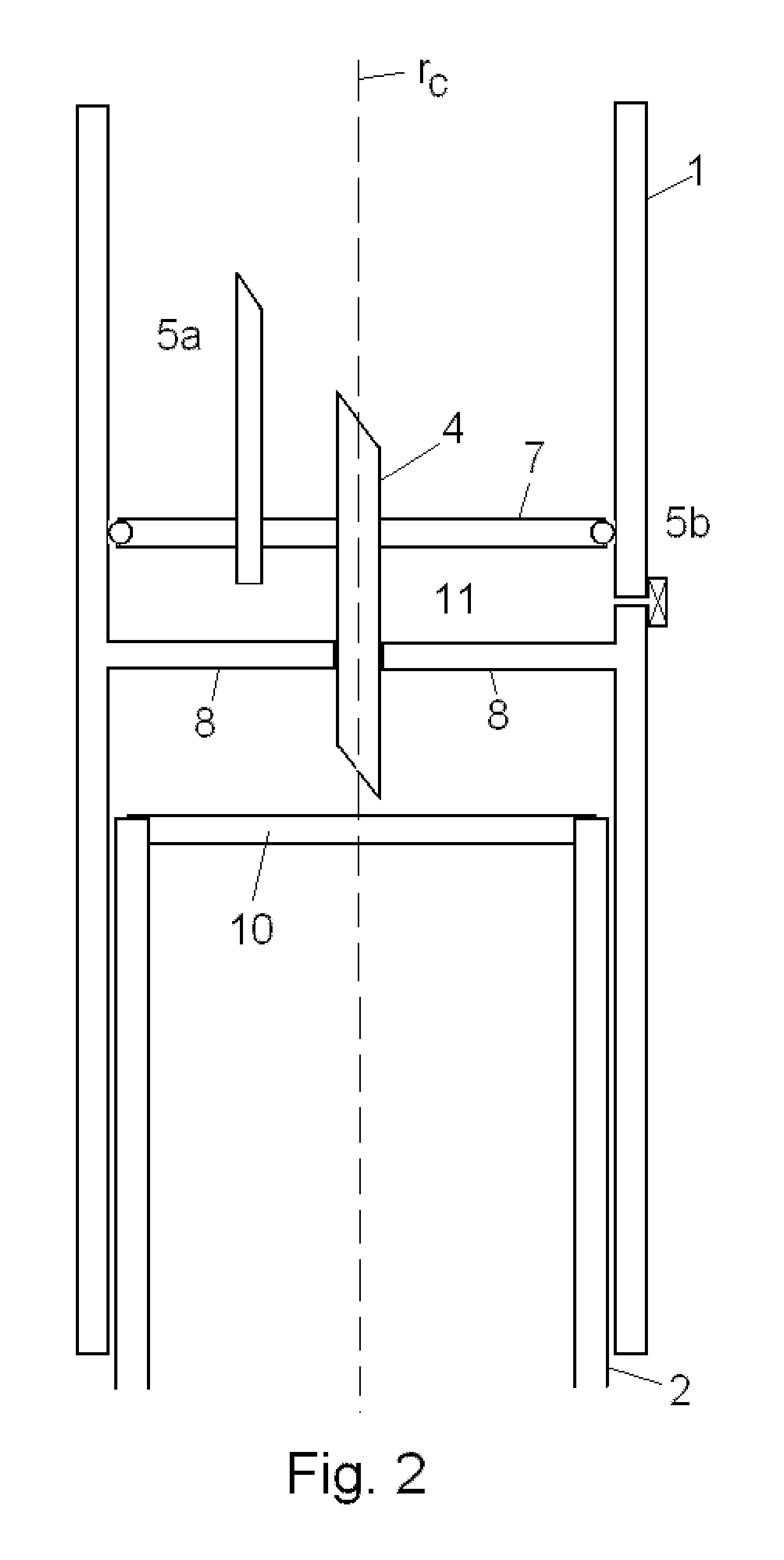
[0005]The object of the invention is to provide a filling device which is easy to handle for the user, simple and non-expensive to manufacture and where the risk of breaking the venting needle during the filling process has been eliminated.

[0006]The invention concerns a filling device which comprising[0007]a housing comprising[0008]a first position means adapted to receive a reservoir for receiving liquid,[0009]a second position means adapted to receive a cartridge containing a liquid,[0010]a unit unreleasably attached to the housing and providing a flow path when both the reservoir and the cartridge are received respectively by the first and second positions means,[0011]a venting unit providing access of gas to the cartridge during emptying of the cartridge, and at least a part of the venting unit is placed off the rotational centre (rc) of the housing and is attached to a part. The invention is characterized in that this part can rotate relative to the housing and relative to the ...


PUM


Abstract

The invention relates to a filling device for a reservoir which reservoir is to be filled from a cartridge such as cartridges having rigid walls e.g. made of glass and provided with a membrane which can be penetrated by a needle for protection of the entrance. According to the present invention the filling device comprises—a housing (1) which housing (1) comprises—a first position means adapted to receive a reservoir (2) for a delivering device,—a second position means adapted to receive a cartridge (3) containing a liquid,—a unit (4) providing a flow path when both the reservoir (2) and the cartridge are received respectively by the first and second positions means,—a venting unit (5, 5a, 5b) providing access of gas to the cartridge (3) during emptying of the cartridge (3). The filling device is characterized in that at least a part of the venting unit (5) is placed off the rotational centre (rc) of the housing and is attached to a part (7) which part (7) can rotate relative to the housing (1).

Description

TECHNICAL FIELD[0001]The invention relates to a filling device for a reservoir which reservoir is to be filled from a cartridge such as cartridges having rigid walls e.g. made of glass and provided with a membrane which can be penetrated by a needle for protection of the entrance.BACKGROUND OF THE INVENTION[0002]Filling devices for reservoirs are known and it is recognized that it can be necessary to vent the container which is to be emptied for filling liquid in order to reduce the costs for filling or refilling of reservoirs.[0003]A problem which arises when manufacturing such filling devices is how to place the venting channel in order not to hamper the filling process or to contaminate the filling liquid which will normally be some kind of medication.[0004]U.S. Pat. No. 4,296,786 discloses a transfer device for use in mixing substances in different containers which containers each are closed by a stopper of resilient material having a puncturable diaphragm. The transfer device c...

Claims


Application Information

Patent Timeline
IPC IPC(8): B65B31/04
CPCA61J1/2089A61J1/2096A61J2001/2013A61J2001/2082A61J2001/2072A61J2001/2075A61J2001/2017A61J1/201A61J1/2013A61J1/2017A61J1/2072A61J1/2075A61J1/2082
Inventor JAKOBSEN, CLAUSJUSTESEN, BOHORDUM, ELO
Owner UNOMEDICAL AS
Why Eureka
Try Eureka