
Power Conversion System and Power Control Method for Reducing Cross Regulation Effect

a power conversion system and cross regulation technology, applied in the field of power conversion systems, can solve the problems of poor stability and cross regulation effect of multi-output frameworks, reduce conversion efficiency, increase the conduction loss of the whole system,

Active Publication Date: 2011-07-14
ALPHA & OMEGA SEMICON CAYMAN
View PDF5 Cites 19 Cited by
  • Summary
  • Abstract
  • Description
  • Claims
  • Application Information

AI Technical Summary

Benefits of technology

The invention is a power conversion system and method that reduces cross regulation effect, which is a problem where multiple output voltages become unstable and unpredictable. The system uses a voltage feedback adjustment circuit to modulate an error signal and eliminate cross regulation effect, resulting in a stable multiple output power. The system also predicts changes in energy of an output voltage based on changes in the load state of the output voltage terminal, and quickly adjusts the duty cycle of the system to achieve excellent output stability and transient response as well as improved power conversion efficiency. The invention can be integrated into various power management modules for various applications. Overall, the invention provides a more stable and efficient power conversion system and method.

Problems solved by technology

However, the multi-output framework has problems of poor stability and cross regulation effect.
However, a Freewheel stage must be added in during the whole PWM period; as the switch is not conducted ideally, a large amount of power can be consumed by the equivalent resistance of switching in this stage; therefore, the Conduction Loss of the whole system can be increased, thereby reducing the efficiency of conversion.
Besides, the energy stored in the inductor during the Freewheel stage can not be transferred to the output terminal and the average inductor current is more than the sum of the output loads.
However, this method is only applicable to a certain specific load sate; moreover, the method uses a comparator to control the output voltage and does not provide a satisfactory overall voltage stabilization effect compared with the effect of a close loop which adopts an error amplifier to control.
Moreover, as the negative-voltage output is achieved by the Charge Pump, the negative-voltage output can have a poor voltage stabilizing situation and is quite undesirable in actual application.

Method used


Image

  • Power Conversion System and Power Control Method for Reducing Cross Regulation Effect
  • Power Conversion System and Power Control Method for Reducing Cross Regulation Effect
  • Power Conversion System and Power Control Method for Reducing Cross Regulation Effect

Examples


Embodiment Construction

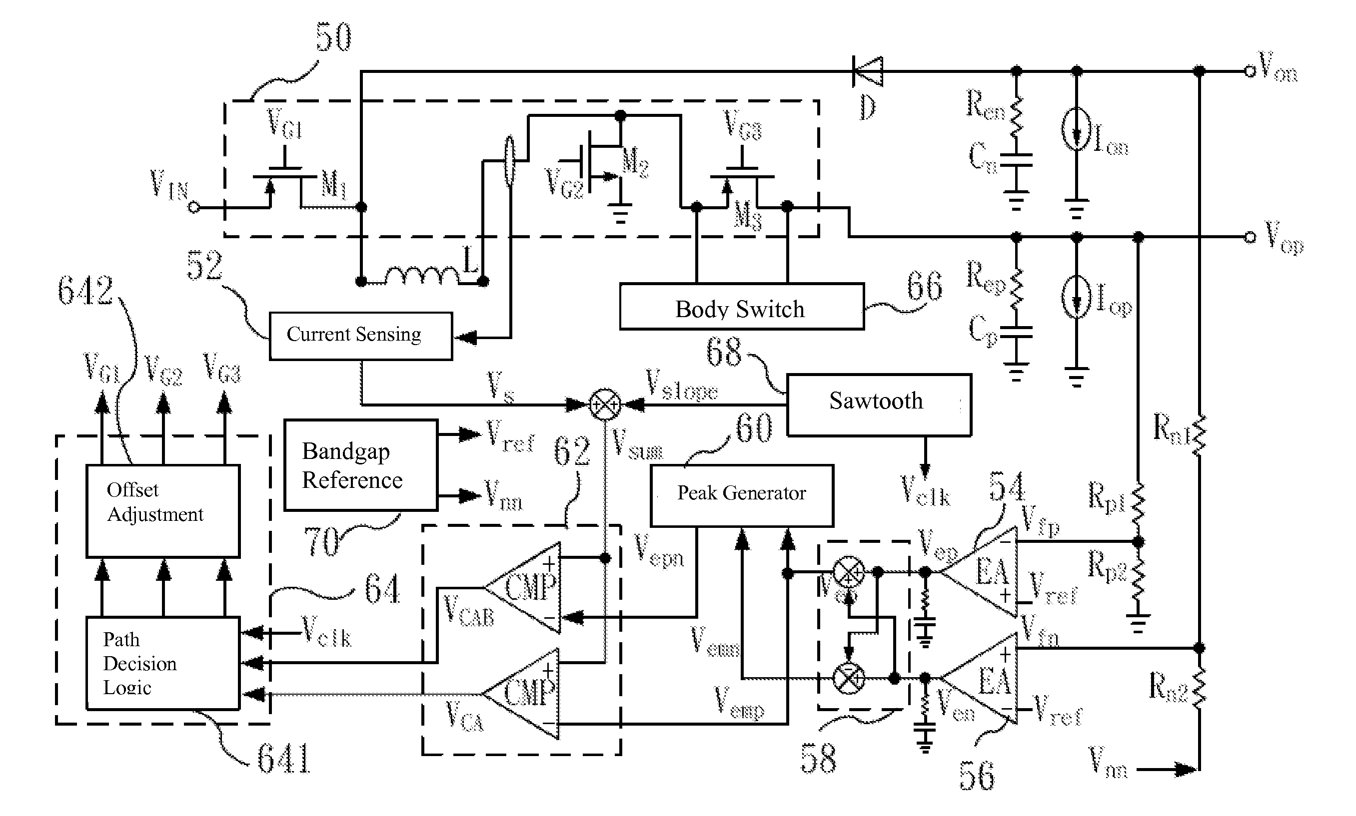
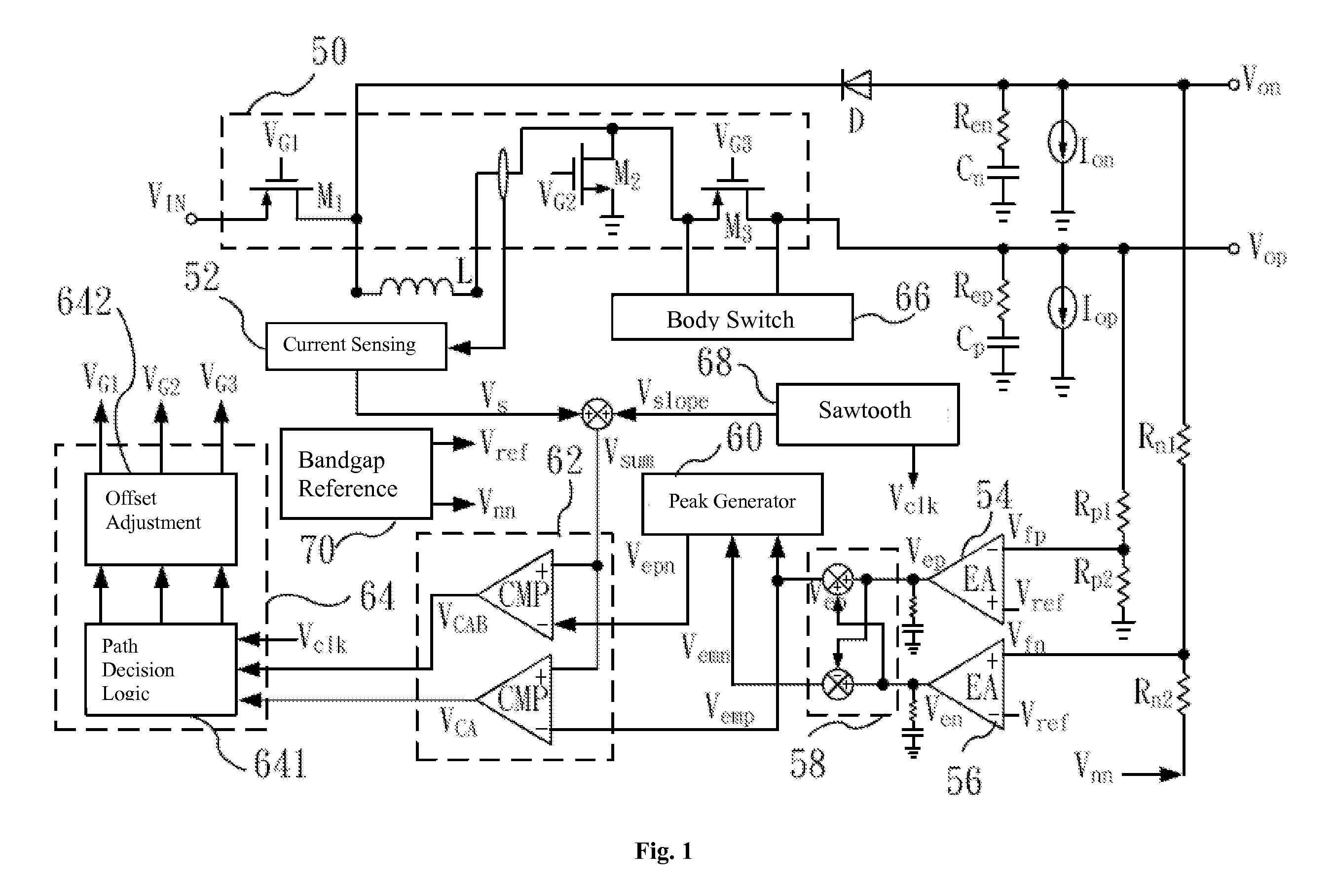
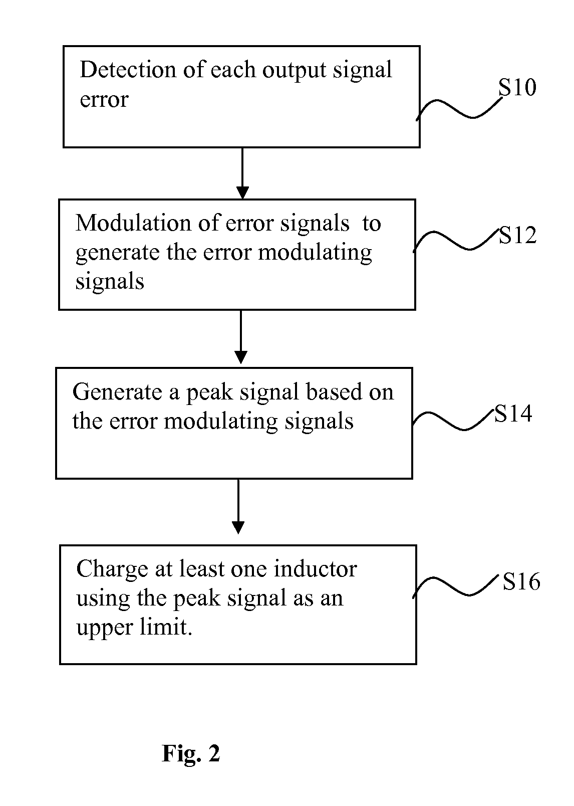
[0019]The invention provides a power conversion system and power control method for reducing cross regulation effect, which uses feedback control to predict the energy of the output voltage when the load state of an output terminal is changed such that the system is capable of adjusting the duty cycle according to the load state change and quickly reaching a steady state therefore reduce the generation of Cross regulation effect. The technical characteristics of the invention are described by preferred embodiments as follows.

[0020]FIG. 1 is a schematic diagram of circuit framework of the invention; as shown in the diagram, a switching circuit 50 is electrically connected with at least one inductor L. The switching circuit 50 comprises a plurality of switching transistors M1, M2 and M3; the inductor L is controlled to be charged and discharged through turning on and off the switching transistors M1, M2 and M3 so as to output a positive output voltage (Vop) and a negative output volta...


PUM


Abstract

A power conversion system and power control method for reducing cross regulation effect uses a voltage feedback adjustment circuit to modulate an error signal fed back from an output voltage so as to predict the energy of an output corresponding to its load states. While the energy delivered to an output terminal with its load remaining the same does not change, the energy delivered to an output terminal with its load changing is adjusted accordingly. The power conversion system thus effectively reduces the cross regulation effect and obtains excellent steady system output and transient response.

Description

[0001]This application is a Continuation in Part of previously filed U.S. application Ser. No. 12 / 686,587, filed on Jan. 13, 2010, the disclosure of which is incorporated hereto by reference in its entirety.FIELD OF INVENTION[0002]The invention relates to a power conversion system, in particular to a power conversion system and power control method for reducing cross regulation effect in a single-inductor multi-output DC / DC converter.BACKGROUND TECHNOLOGIES[0003]Nowadays semiconductor power management chips are broadly applied to portable electronic products like mobile phones, PDAs, notebook computers, etc. In a development trend of system on chips the framework of single-inductor multi-output DC / DC converter is adopted in order to reduce the chip size. However, the multi-output framework has problems of poor stability and cross regulation effect.[0004]Traditionally, multi-outputs are mutually separated such that the output terminals are not interfered by the change of other loads ...

Claims


Application Information

Patent Timeline
Patent Type & Authority Applications(United States)
IPC IPC(8): G05F1/10
CPCH02M3/157H02M2001/009H02M3/158H02M1/009
Inventor WU, JEAN-SHINCHEN, KE-HORNG
Owner ALPHA & OMEGA SEMICON CAYMAN
Learn More