Vein pattern recognition based biometric system and methods thereof

a biometric authentication and pattern recognition technology, applied in the field of vein pattern recognition based biometric authentication system, can solve the problems of system constricting and uncomfortable for a person with a larger hand, not only of image transformation but also of illumination, and not ensuring that the user consistently places his hand

Inactive Publication Date: 2011-07-14
PULLURU KRANTHI KIRAN +2
View PDF26 Cites 35 Cited by
  • Summary
  • Abstract
  • Description
  • Claims
  • Application Information

AI Technical Summary

Benefits of technology

[0039]Still another object of the present invention is to provide an imaging unit to capture an infra-red image of the back of the palm and optical arrangement for uniform lighting even in the presence of ambient light by exploiting the auto-iris effect of the camera.

Problems solved by technology

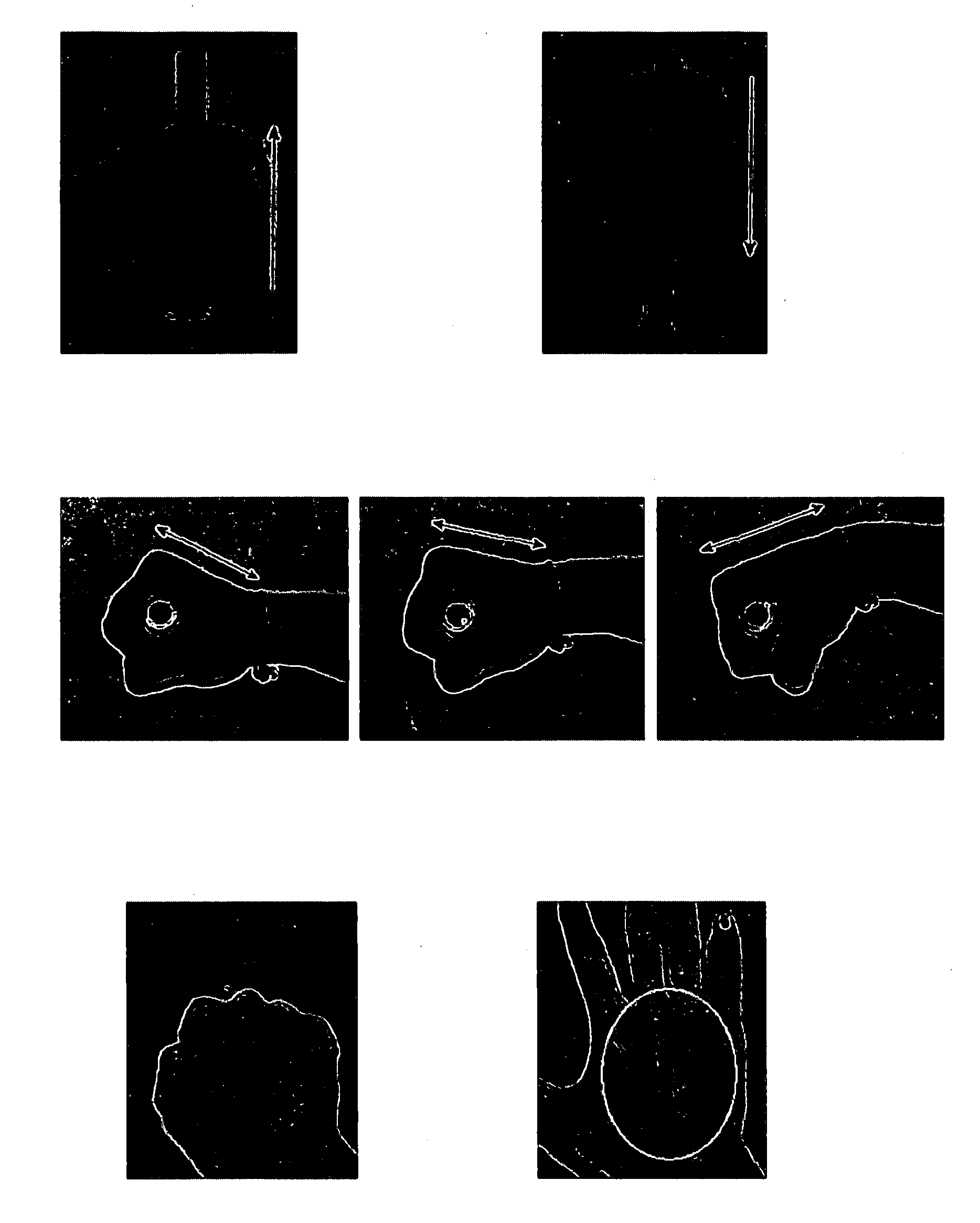
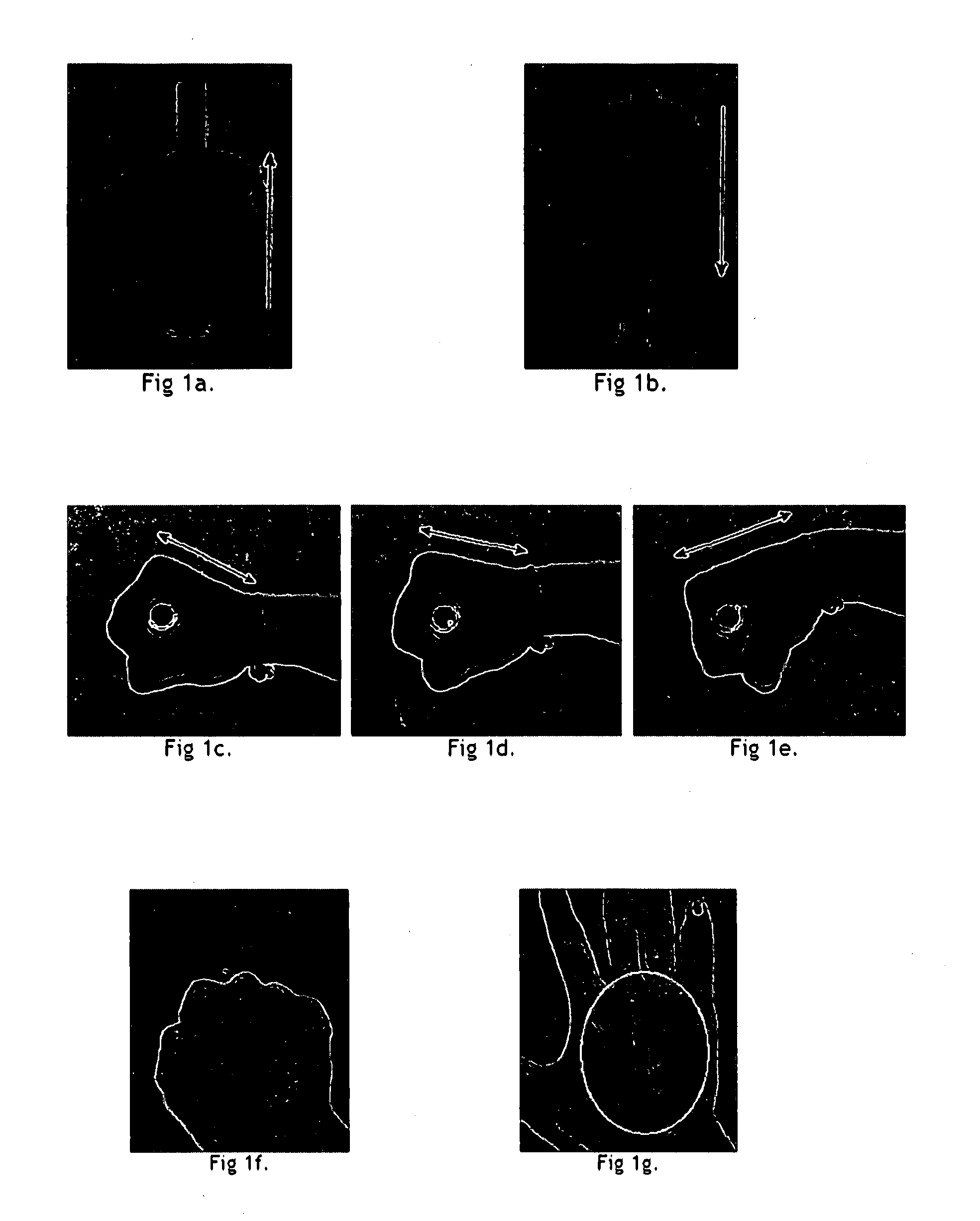
These constructions ensure that the wrist is facing the camera, but they do not ensure that the user consistently places his hand in the same manner because there is enough leeway for movement and rotation of the hand and as shown in the figures.
If the holding bar is made shorter to remove this freedom of movement, the system would become constricting and uncomfortable for a person with a larger hand.
The problem is not only of an image transformation but also of illumination, as the light reflected from the hand also changes in these situations.
These variations cause distortions in the resulting vein pattern.
R8 mentions that room light can be used as infra-red source, but in an indoor environment during night there isn't sufficient IR that can be captured by a CCD camera.
The system employs a setup of multiple reflectors, diffusers and polarizers which makes the system bulky and hence non-portable.
A low cost diffuser reduces the intensity of light making the image dull and increasing the intensity requires an array of LEDs which increase the cost of the device.
Light correcting diffusers give better results but are expensive.
Such an iterative approach is time consuming.
In a real life situation such delays lead to user annoyance.
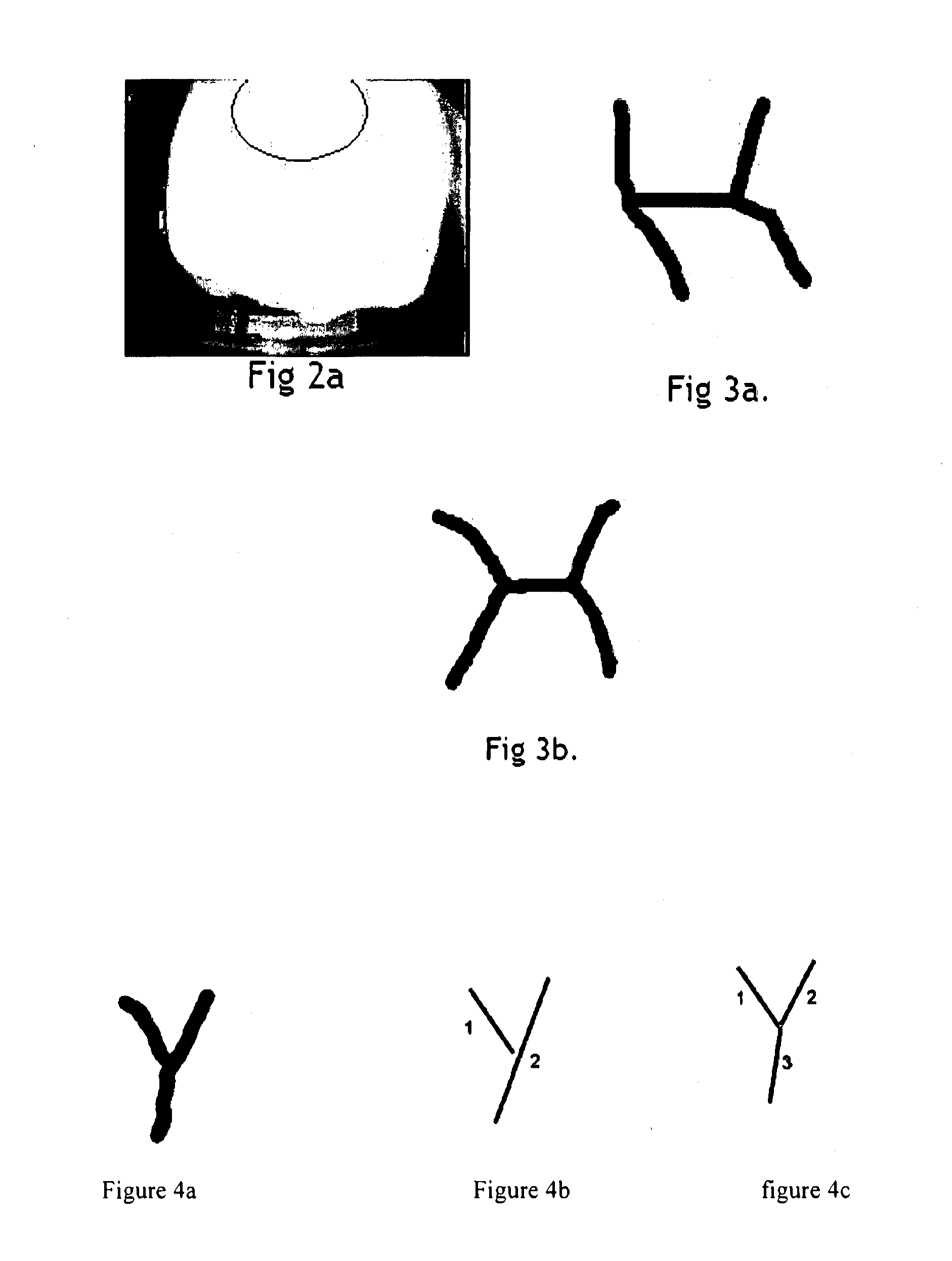
The problem with thinning is that vital information about the width of the veins is lost.
Also the drawback of using a method based solely on the binarized image is that the directionality and continuity of the vein pattern are not fully exploited.
The problem with such a method is there could be alternate representations of the same pattern in terms of line segments.

Method used


Image

  • Vein pattern recognition based biometric system and methods thereof
  • Vein pattern recognition based biometric system and methods thereof
  • Vein pattern recognition based biometric system and methods thereof

Examples


Embodiment Construction

[0069]In the following detailed description, reference is made to the accompanying drawings, which forms a part hereof. In the drawings, similar symbols typically identify similar components, unless context dictates otherwise. The illustrative embodiments described in the detailed description, drawings, and claims are not meant to be limiting. Other embodiments may be utilized, and other changes may be made, without departing from the spirit or scope of the subject matter presented herein. It will be readily understood that the aspects of the present disclosure, as generally described herein, and illustrated in the figures, can be arranged, substituted, combined, separated, and designed in a wide variety of different configurations, all of which are explicitly contemplated herein.

[0070]An illustrative embodiment provides vein pattern recognition based biometric system. The biometric system includes but not limited to a hand placement unit, and detection unit being configured to info...


PUM


Abstract

Individual authentication techniques are disclosed, which relate to a vein recognition based to biometric authentication system. Systems and methods to capture the subcutaneous vein pattern at the back of the palm and use it as the biometric identity of an individual are also disclosed.

Description

TECHNICAL FIELD[0001]The present disclosure generally relates to a biometric authentication techniques, particularly relates to a vein recognition based to biometric authentication system, more particularly, it relates to a system and methods to capture the subcutaneous vein pattern at the back of the palm and use it as the biometric identity of an individual.BACKGROUND OF THE INVENTION AND PRIOR ART[0002]A biometric system based on the recognition of veinous pattern on the palm or the back of the hand is generally a combination of the following modules and their operations[0003]U1. A Hand Placement and Detection Unit: the purpose of which is to detect the presence of a hand when the user places his hand on it in a certain manner. The detection unit informs the computer about the presence of a hand and prompts it for further processing.[0004]U2. Illuminating and Imaging unit: The purpose of this unit is to illuminate the region of interest with uniformly diffused near-infrared light...

Claims


Application Information

Patent Timeline
Patent Type & Authority Applications(United States)
IPC IPC(8): G06K9/00H04N7/18
CPCG06F21/32G06K9/00006H04L63/0861G06K2009/00932G06K9/00919G06V40/12G06V40/63G06V40/14G07C9/00G06F18/00H04L9/40
Inventor PULLURU, KRANTHI KIRANAGRAWAL, GOVINDAGRAWAL, ARTI
Owner PULLURU KRANTHI KIRAN
Why Eureka
Try Eureka