
Electronic assembly and method of manufacturing same

a technology of electronic assembly and assembly method, which is applied in the direction of electrical apparatus casing/cabinet/drawer details, coupling device connections, casings/cabinets/drawers, etc., can solve the problems of high cost of enclosure with insert molded connector terminals and difficulty in forming connections

Active Publication Date: 2011-07-14
TRW AUTOMOTIVE US LLC
View PDF2 Cites 28 Cited by
  • Summary
  • Abstract
  • Description
  • Claims
  • Application Information

AI Technical Summary

Benefits of technology

"The present invention relates to an electronic assembly and a method of manufacturing the assembly. The assembly includes a housing, a printed circuit board, and a compliant pin header assembly. The compliant pin header assembly includes a header with passages for receiving compliant pins. The compliant pins have a flat surface for engaging the housing and the printed circuit board. The method includes steps of inserting the compliant pins into the housing and engaging the printed circuit board with the compliant pins. The assembly and method provide improved reliability and stability during assembly and use."

Problems solved by technology

Because the connector is mounted on the PCB, difficulties may arise in achieving desired alignment between the connector for the electronic assembly and an external, mating connector, which together electrically connect the electronic assembly to other portions of the vehicle circuitry.
Such an enclosure with insert molded connector terminals is expensive as it requires unique tooling and assembly equipment for each particular vehicle application.

Method used


Image

  • Electronic assembly and method of manufacturing same
  • Electronic assembly and method of manufacturing same
  • Electronic assembly and method of manufacturing same

Examples


Embodiment Construction

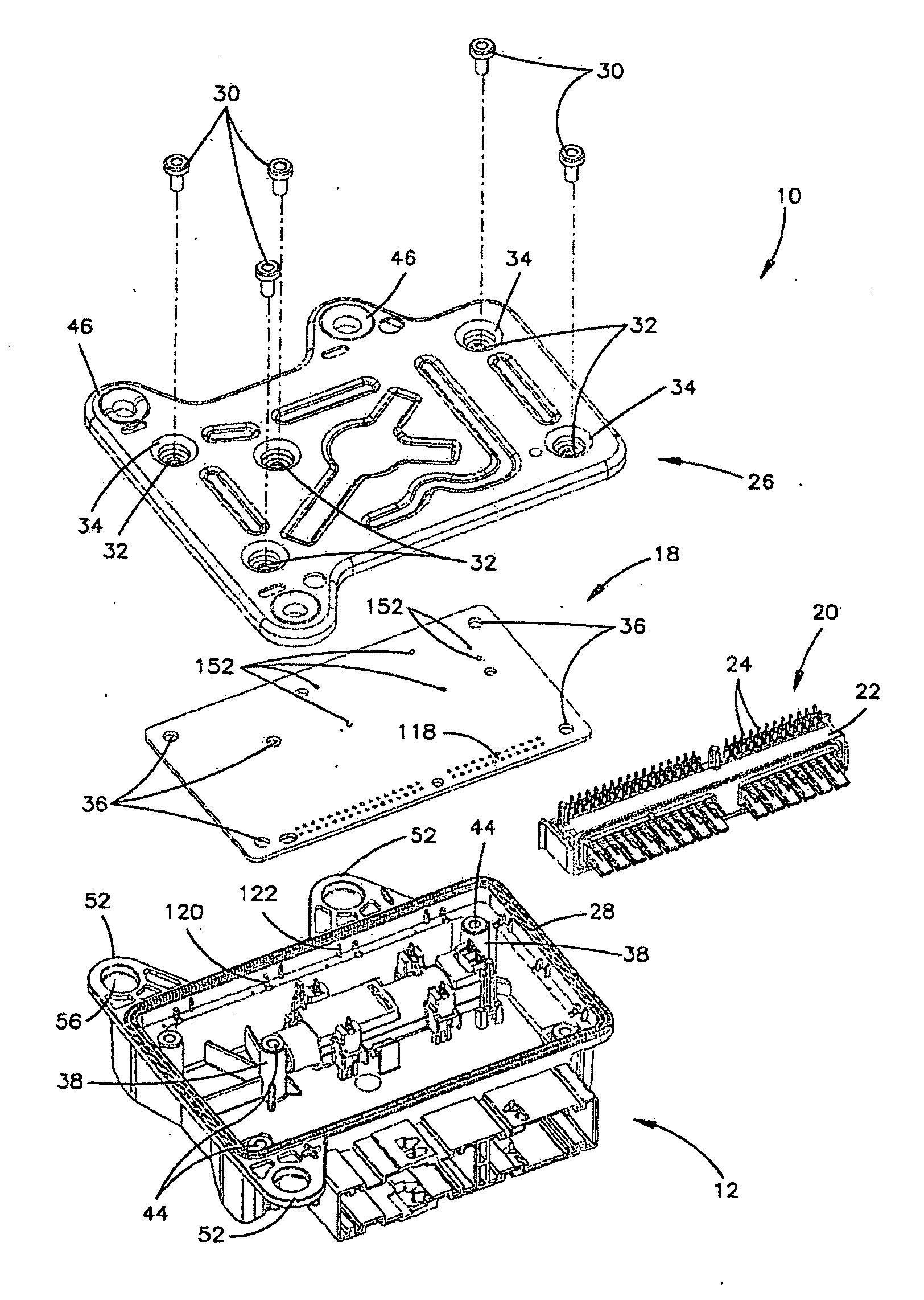
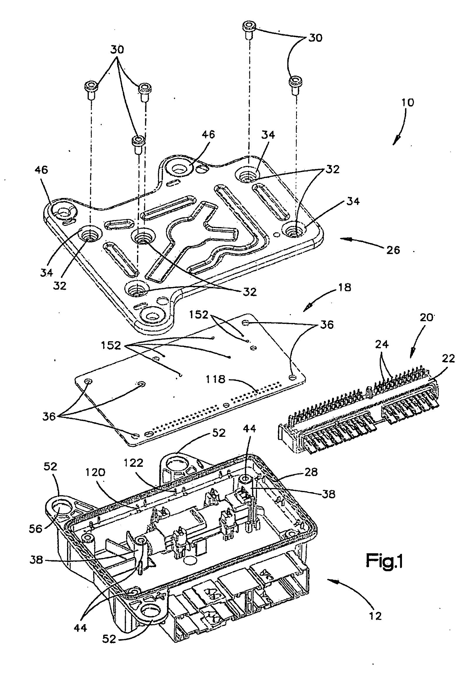
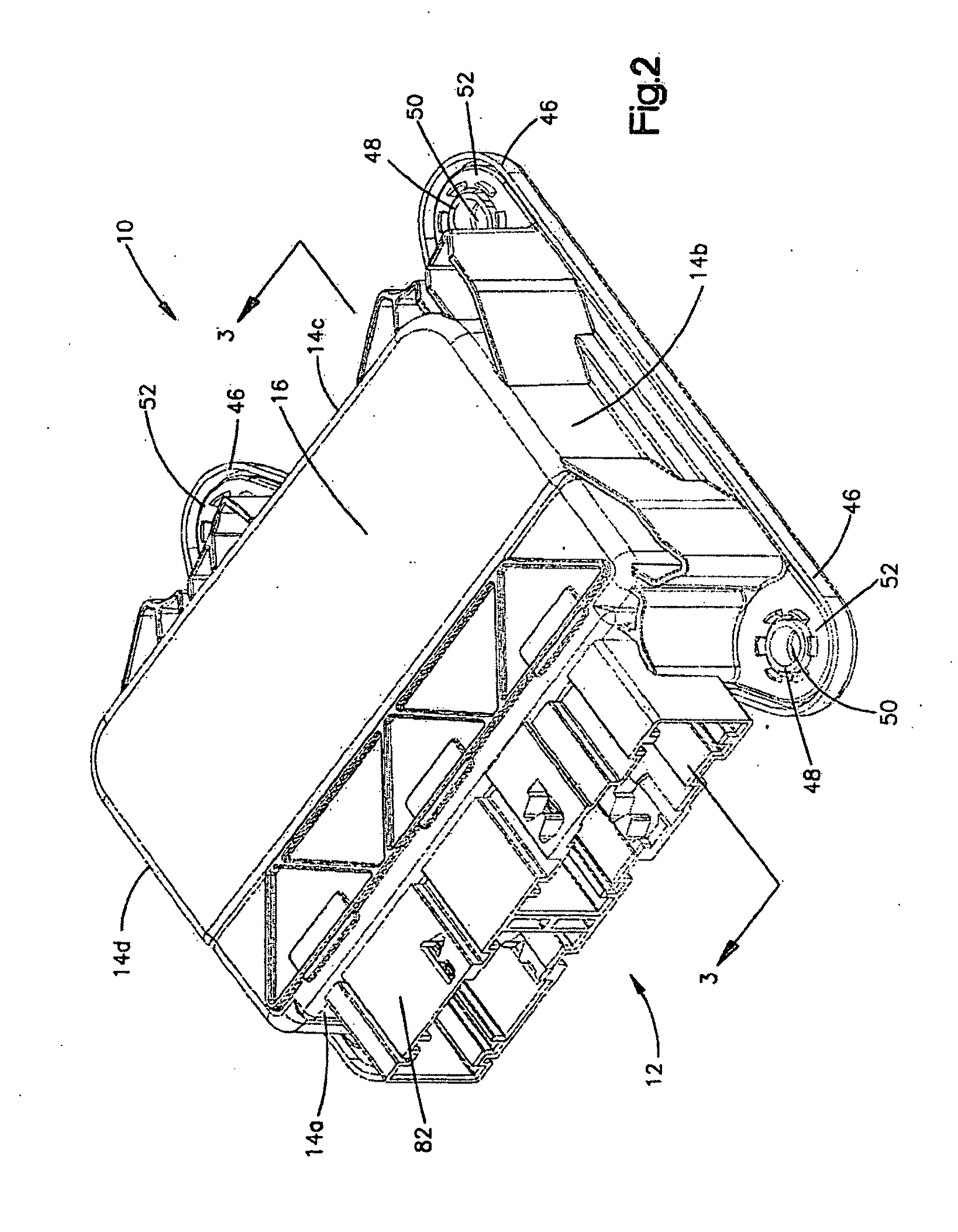
[0027]Referring to FIGS. 1 through 3, an electronic assembly 10 in accordance with an example embodiment of the present invention is shown. The electronic assembly 10 includes a plastic housing 12. The plastic housing 12 is a one-piece molded unit with four housing side walls 14a-14d and a top 16 and may be lighter in weight than a comparably sized metal housing. The plastic housing 12 receives a printed circuit board (“PCB”) 18 and a separate compliant pin header assembly 20. The compliant pin header assembly 20 is snapped in place in the housing. The PCB 18 is pressed onto the compliant pin header assembly 20, as will be described in greater detail below. The compliant pin header assembly 20 includes a compliant pin header 22 and two rows of compliant pins or terminals 24. The compliant pin header 22 is a molded plastic part, and the compliant pins or terminals 24 may be “stitched into” the pin header, rather than being insert molded in the Pin header. A portion of the compliant p...


PUM

PropertyMeasurementUnit
electrically conductiveaaaaaaaaaa
forceaaaaaaaaaa
distanceaaaaaaaaaa

Abstract

An electronic assembly comprises a housing, a cover for the housing, a printed circuit board receivable in the housing, and a compliant pin header assembly. The compliant pin header assembly is moimtabie in the housing by inter-engaging features on the header assembly and the housing. The compliant pin header assembly has compliant pins for engaging corresponding features on the printed circuit board to connect the compliant pin header assembly electrically to the printed circuit board. The cover, when the electronic assembly is assembled, engages the housing and also engages the printed circuit board at a location spaced from an outer periphery of the printed circuit board.

Description

RELATED APPLICATIONS[0001]This application claims priority from U.S. Provisional Application No. 61 / 008,393, filed Dec. 20, 2007.TECHNICAL FIELD[0002]The present invention relates to an electronic assembly and a method of manufacturing the electronic assembly and, more particularly, to an electronic assembly that includes a printed circuit board and a method of manufacturing such an electronic assembly.BACKGROUND OF THE INVENTION[0003]It is known to provide an enclosure for an electronic assembly that includes a printed circuit board and a connector. For example, electronic modules and sensors for automotive applications often include a multi-piece (e.g., housing and cover) enclosure for their electronic components, together with a connector that is mounted on a printed circuit board (“PCB”). Because the connector is mounted on the PCB, difficulties may arise in achieving desired alignment between the connector for the electronic assembly and an external, mating connector, which tog...

Claims


Application Information

Patent Timeline
Patent Type & Authority Applications(United States)
IPC IPC(8): H05K5/02
CPCH01R13/447H01R43/18H01R23/7073H01R2201/26H05K5/003H05K5/0047H01R43/205H05K5/006H01R12/724H01R13/506H05K5/0052Y10S439/941Y10T29/49204H01R43/20H02G3/086H02G3/16H01R13/41Y10T29/49117Y10T29/49222Y10T29/49208Y10T29/4922Y10T29/49002H01R43/16H01R13/6658H01R12/00H05K7/1428H05K5/03
Inventor BLOSSFELD, MIKESANCHEZ, LUIS FERNANDO
Owner TRW AUTOMOTIVE US LLC
Learn More