Diesel engine

a technology of diesel engines and exhaust gas, which is applied in the direction of machines/engines, electrical control, mechanical equipment, etc., can solve the problems of affecting the performance of diesel engines, and affecting the operation of diesel engines. , to achieve the effect of preventing unnecessary fuel consumption, preventing engine stalls, and avoiding discomfor

Inactive Publication Date: 2011-07-21
YANMAR POWER TECHNOLOGY CO LTD
View PDF8 Cites 15 Cited by
  • Summary
  • Abstract
  • Description
  • Claims
  • Application Information

AI Technical Summary

Benefits of technology

[0013]The embodiments of the present invention provide the following advantageous effects.
[0014]According to the embodiment recited in claim 1, it is possible to regenerate the particulate filter without exerting any effect on workability of the diesel engine, and thus to eliminate discomfort when an operator is at work.
[0015]According to the embodiment recited in claim 2, under the isochronous control, no unnecessary regeneration load is applied in a low rotational range of the diesel engine below the regeneration enabling area, making it possible to prevent unnecessary consumption of fuel.
[0016]According to the embodiment recited in claim 3, when the maximum torque line is exceeded by application of the regeneration load, no regeneration load is applied, making it possible to prevent an occurrence of engine stall unexpected by an operator.

Problems solved by technology

Meanwhile, since the particulates are accumulated inside the porous walls, an increase in exhaust resistance and a rise in differential pressure between the inlet side and outlet side of the particulate filter occur to exert adverse effects on performance of the diesel engine.
However, there has been a problem in that particulates are not combusted and removed when the load of the diesel engine is low and the temperature of an exhaust gas is low.

Method used


Image

  • Diesel engine
  • Diesel engine
  • Diesel engine

Examples


Embodiment Construction

[0023]Next, embodiments of the present invention will be described.

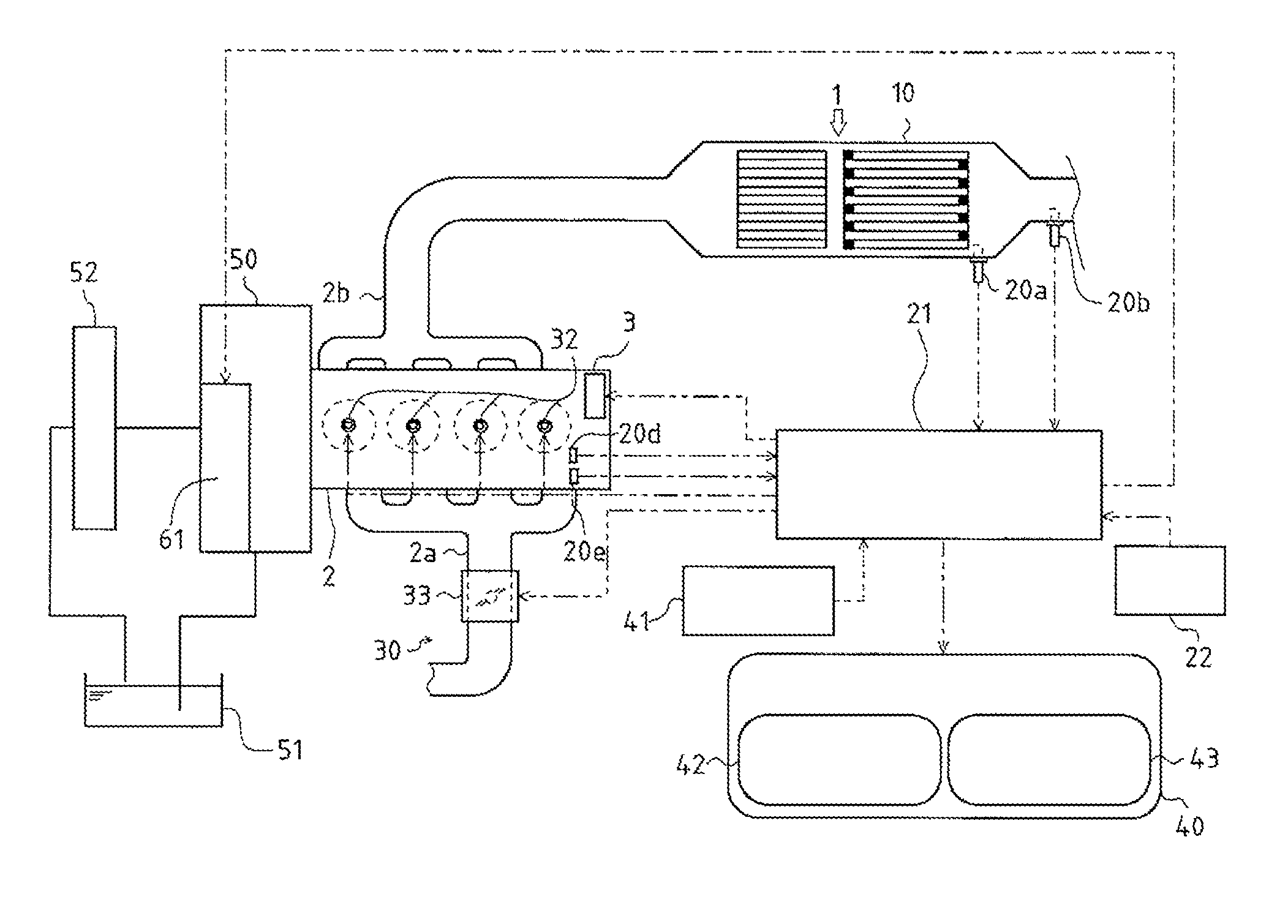
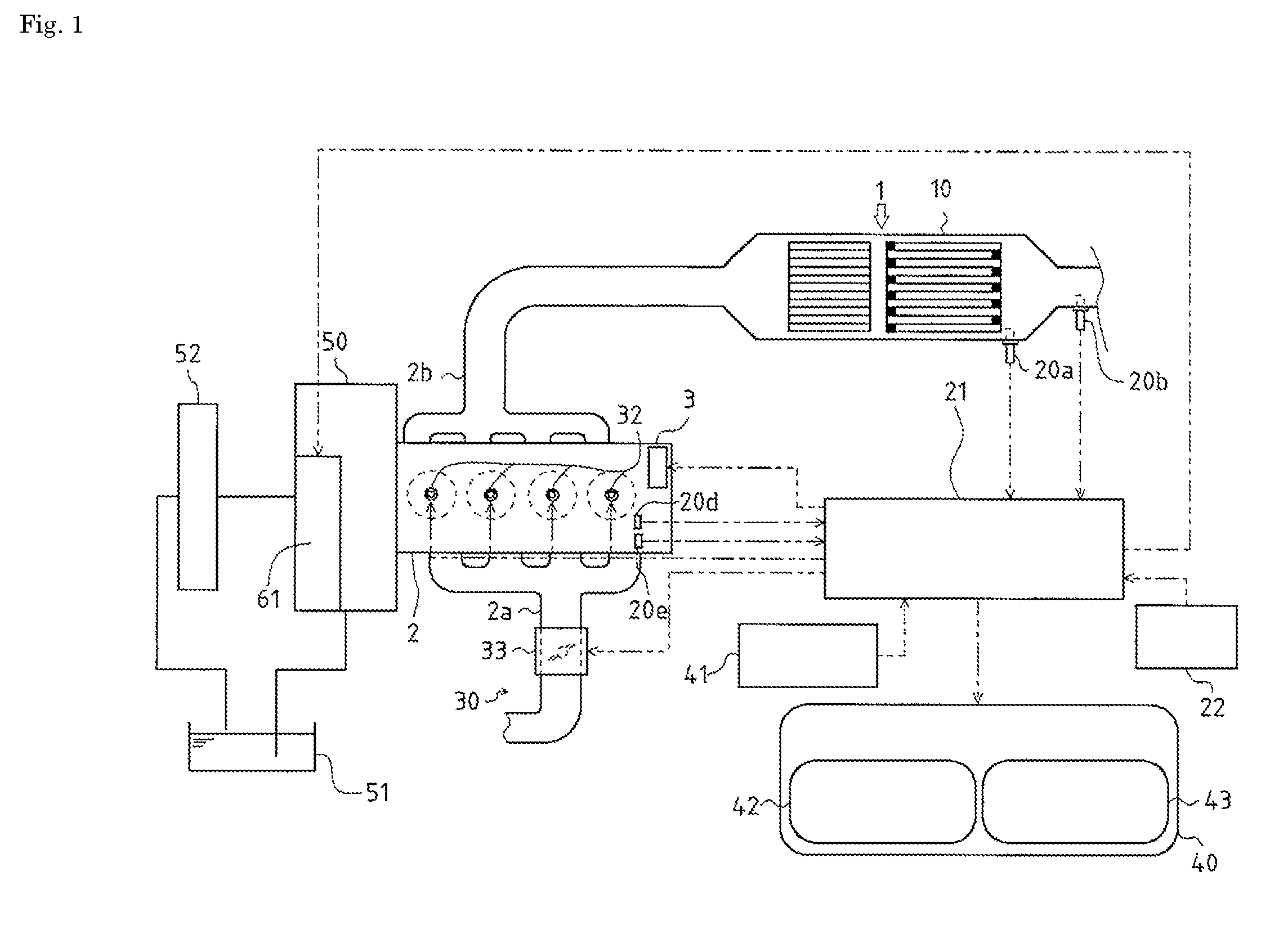
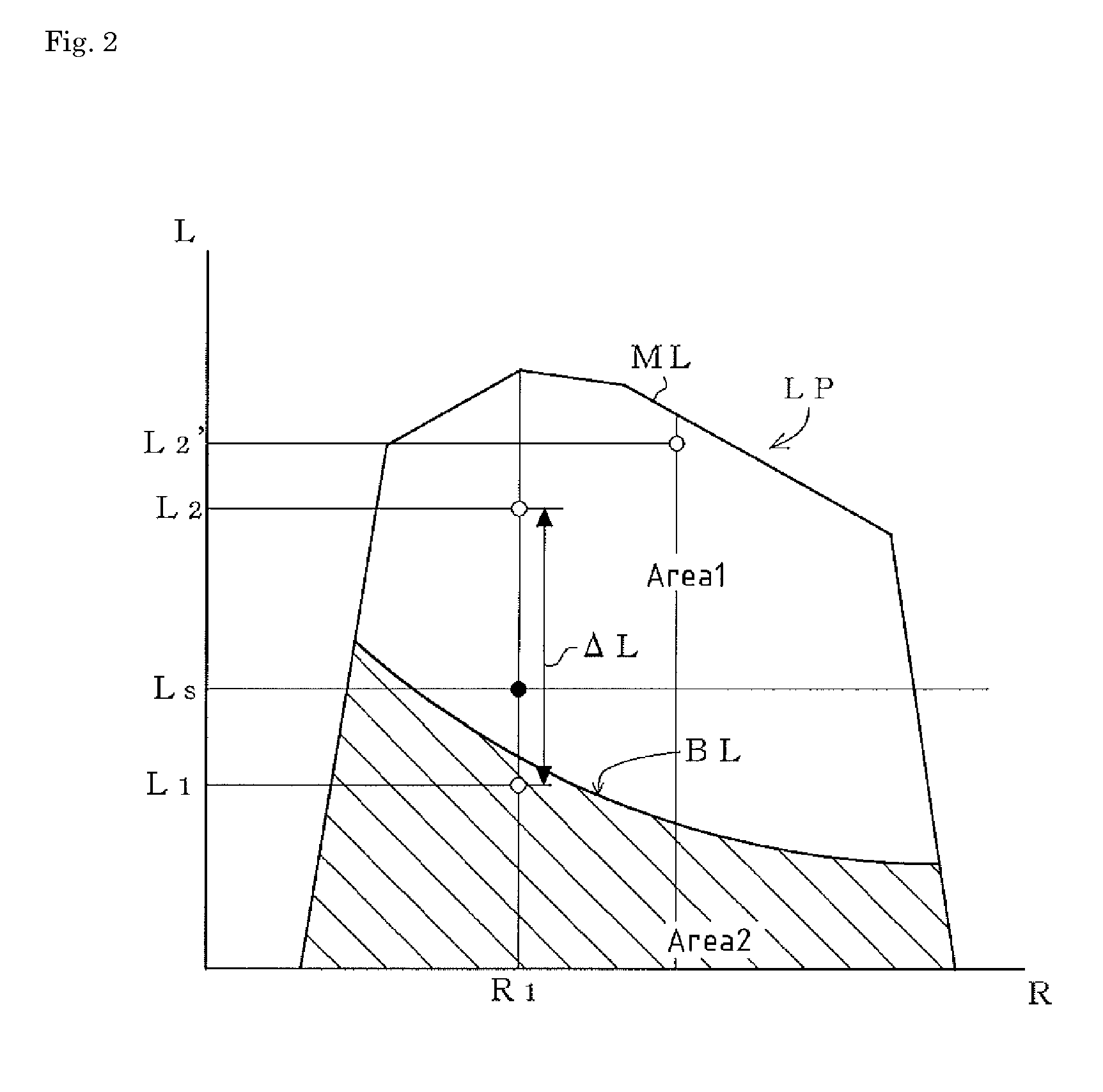
[0024]FIG. 1 is a functional block diagram illustrating a general arrangement of a diesel engine and an exhaust emission purifier according to one embodiment of the present invention. FIG. 2 is a diagram illustrating a relationship between engine load and engine rotational speed. FIG. 3 is a flowchart of filter regeneration control. FIG. 4 is a diagram illustrating a relationship between engine load and engine rotational speed. FIG. 5 is a diagram illustrating a relationship between engine load and engine rotational speed. FIG. 6 is a diagram illustrating a relationship between engine load and engine rotational speed.

[Configuration of the Exhaust Emission Purifier]

[0025]As shown in FIG. 1, a diesel-engine exhaust emission purifier 1 is included in a diesel engine 2 that is one embodiment of a diesel engine according to the present invention. The exhaust emission purifier 1 purifies exhaust gas generated in the diesel...


PUM


Abstract

An object is to provide a diesel engine (2) that eliminates discomfort when an operator of a working machine coupled to the diesel engine (2) is at work while a particulate filter (10) is being regenerated. A diesel engine (2) includes an exhaust emission purifier (1) and selecting means (41) capable of selecting any one control method from isochronous control and droop control. The exhaust emission purifier (1) includes a particulate filter (10) and a pressure regulation valve (61). The particulate filter (10) is disposed along an exhaust stream to purify exhaust gas. The pressure regulation valve (61) is configured to apply a load onto the diesel engine (2) so as to raise a temperature of the particulate filter (10) so that a particulate accumulable in the particulate filter (10) is forcibly removed and that the particulate filter (10) is regenerated. The selecting means (41) is configured to select the isochronous control to control the diesel engine (2) when the load is applied by the pressure regulation valve (61).

Description

TECHNICAL FIELD[0001]The present invention relates to a technique regarding diesel engines, and more particularly, to a technique regarding a diesel engine having an exhaust emission purifier.BACKGROUND ART[0002]Conventionally, as a technique to trap particulates contained in exhaust gas discharged from a diesel engine, a technique has been known that an engine exhaust emission purifier including a particulate filter is equipped along an exhaust stream of a diesel engine. The particulate filter has a porous honeycomb structure made of ceramics or other material, and the particulate filter has a configuration in which inlets of respective flow paths defined in a lattice form are alternately sealed up while outlets of flow paths whose inlets are unsealed are sealed up, to discharge only exhaust gas that has permeated through porous walls defining the respective flow paths to a down-stream.[0003]Exhaust gas is purified such that particulates in the exhaust gas are trapped inside the po...

Claims


Application Information

Patent Timeline
Patent Type & Authority Applications(United States)
IPC IPC(8): F02D43/00
CPCF01N9/002F01N2250/02F01N2430/00F01N13/0097F02D2250/18Y02T10/47F02D41/029Y02T10/40F01N3/02F02D45/00
Inventor MASUDA, HIROSHIHARA, MICHIHIKO
Owner YANMAR POWER TECHNOLOGY CO LTD
Why Eureka
Try Eureka