Multipurpose utility vehicle

a multi-purpose, utility vehicle technology, applied in the field of vehicles, can solve the problems of limiting the use of the tractor, restricting the visibility of the front of the tractor, and prior vehicles without adequate flexibility, and achieve the effect of reducing oscillations

Active Publication Date: 2011-07-21
HUHN MICHAEL CARL +1
View PDF48 Cites 4 Cited by
  • Summary
  • Abstract
  • Description
  • Claims
  • Application Information

AI Technical Summary

Benefits of technology

[0004]In a preferred embodiment, the invention is a vehicle providing a unique combination of a forward mounted, mid-mounted drive train, and axle suspension system to create a multi-application work vehicle with excellent visibility and utility. For example, the vehicle of the invention can be used for agricultural, construction or municipal applications.
[0005]The operator's cab of the preferred vehicle has windows extending over the majority of the height of the cab and in one embodiment over virtually the entire height of the cab. The cab is mounted to the frame over the front axle by rubber mounts and provides excellent visibility of the area in front of the vehicle. The Cab may be tilted forward to provide access to the frame and front axle for maintenance.
[0007]The engine and transmission are mounted in the frame opening in the mid section of the frame to evenly distribute the weight of these components and to provide a low center of gravity. The frame is preferably internally reinforced whereby it is rigid to reduce fatigue cracking of the equipment attached to the frame.
[0008]The narrower front and back portions of the frame provide clearance for the wheels during steering of the vehicle but also maintain a legal overall road width for the vehicle.
[0010]Hydraulic cylinders are provided between the movable ends of the arms and the frame to support the weight of the vehicle and to dampen oscillations. Electronic height sensors are also provided to detect the position of the arms and to provide that information electronically to a controller to raise or lower the suspension to maintain a desired vehicle height.

Problems solved by technology

While vehicles having such components are known, prior vehicles do not have adequate flexibility and are typically single use vehicles.
This configuration greatly restricts visibility of the front of the tractor.
Moreover, the frame of such a vehicle is typically configured to engage an object to be towed, such as a trailer, only from the rear, which restricts its use.
Such vehicles are not capable of being used for a variety of purposes.
Vehicles configured to place the operator cab toward the front are known, but these typically place the engine beneath the cab, which restricts the uses that can be made of the frame in the area beneath the cab.

Method used


Image

  • Multipurpose utility vehicle
  • Multipurpose utility vehicle
  • Multipurpose utility vehicle

Examples


Embodiment Construction

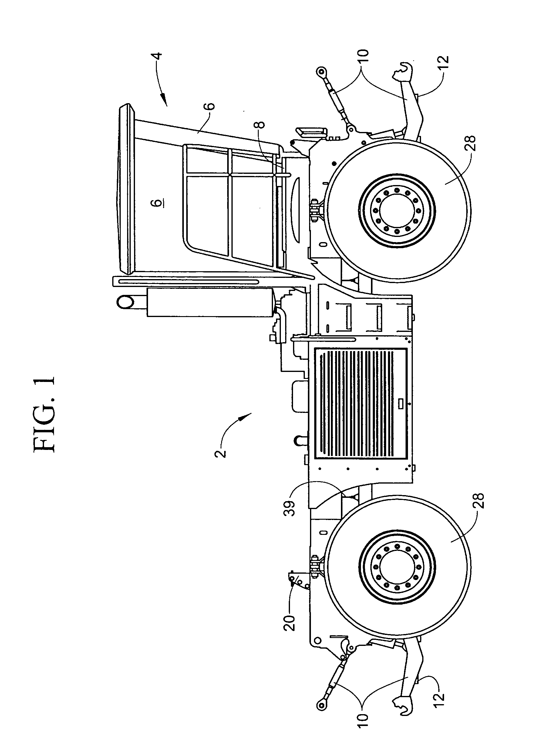
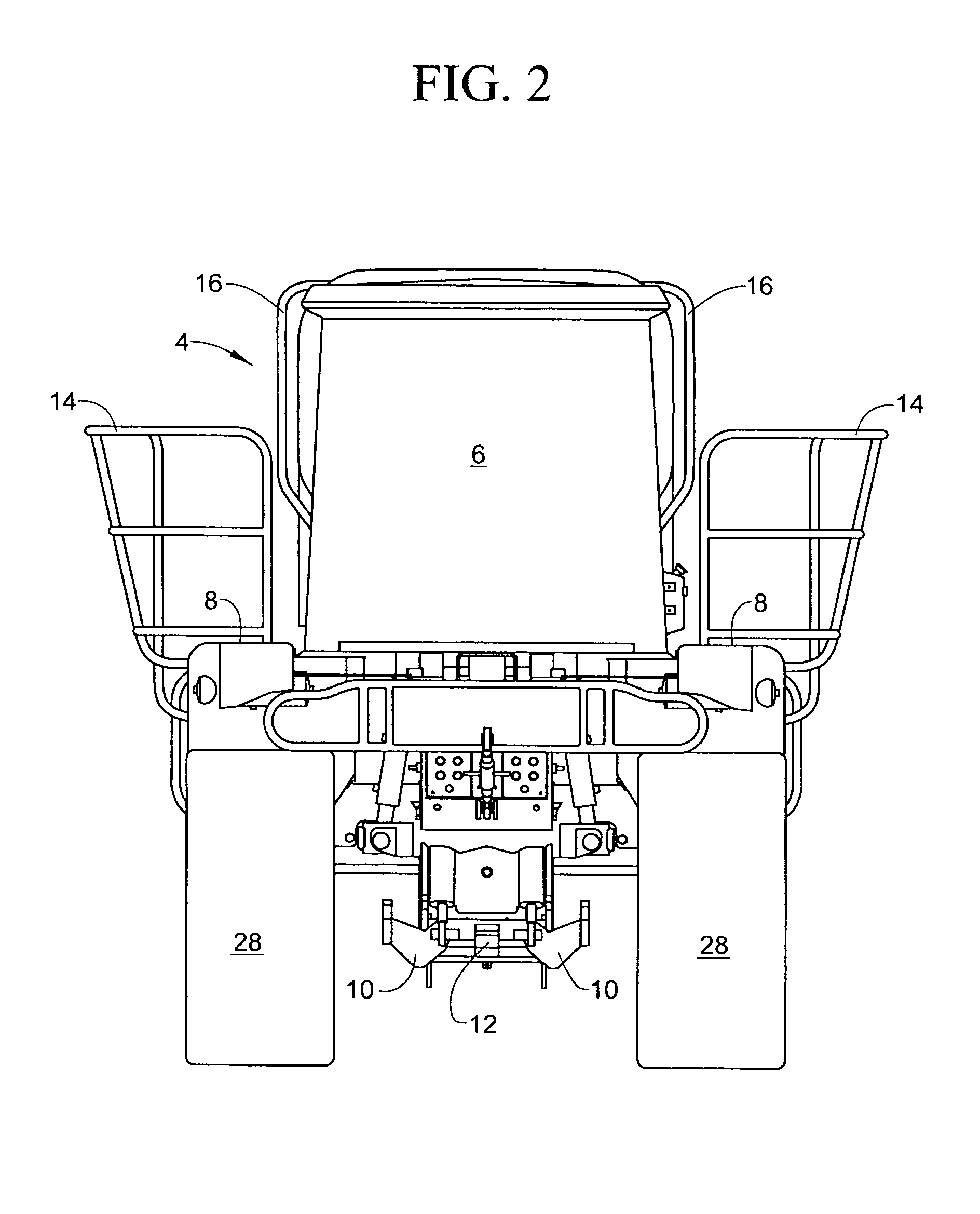
[0017]With reference to FIG. 1, a vehicle 2 in accordance with the invention comprises an operator's cab portion 4 that is mounted toward one end of a frame, which will be more described in more detail below. The cab 4 preferably provides windows 6 that extend essentially the full height of the cab to form an enclosure for the operator while providing increased visibility for the operator.

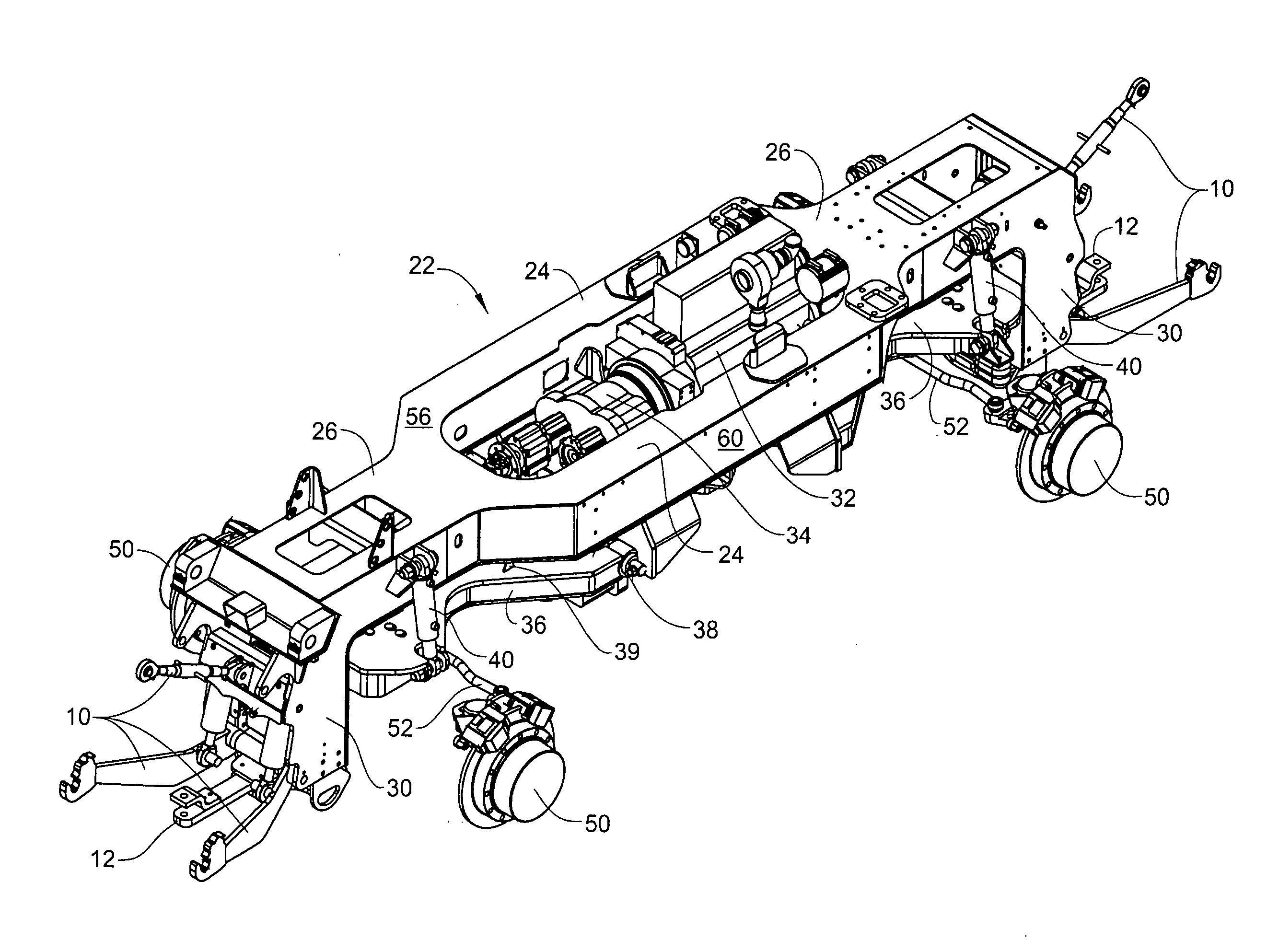
[0018]Platforms 8 are located on either side of the cab 4 and provide walkways for the operator and for technicians performing maintenance on the frame or engine when the cab is pivoted clockwise when viewed from FIG. 1 (not illustrated). A three-point hitch 10 and a tongue hitch 12 are attached to each end of the frame whereby the vehicle may be used to tow other vehicles, trailers, etc. from either end of the vehicle.

[0019]FIG. 2 shows the side rails 14 and hand rails 16, which provide safety for the operator when entering or exiting the cab.

[0020]FIG. 3 shows the vehicle 2 of FIG. 1 with a dump ...


PUM


Abstract

A multiuse vehicle comprises a frame having longitudinal portions forming a central opening for supporting an engine and end portions extending forward and rearward from said longitudinal portions, each of the end portions having a downwardly extending leg portion with one or more hitches. A suspension system includes the use of pivoting arms that carry trunnion-mounted differentials. An operator's cab is mounted on a forward portion of the frame to provide the operator with increased visibility. The frame behind the operator's cab is configured to receive any of a variety of devices such as a dump bed, a sprayer tank, a salt spreader, or a flat bed.

Description

TECHNICAL FIELD[0001]This invention relates to the art of vehicles and, in particular, to a configuration for a vehicle that may be used for a variety of purposes.BACKGROUND ART[0002]Vehicles used for farming or industrial uses are well known. These vehicles typically include a frame, an engine, a transmission, axles, an operator cab, and, optionally, utility structure such as a dump bed, a sprayer, or the like. While vehicles having such components are known, prior vehicles do not have adequate flexibility and are typically single use vehicles. For example, in a known farm tractor configuration the engine is placed toward the front of the vehicle while the operator cab is placed toward the rear. This configuration greatly restricts visibility of the front of the tractor. Moreover, the frame of such a vehicle is typically configured to engage an object to be towed, such as a trailer, only from the rear, which restricts its use. Such vehicles are not capable of being used for a varie...

Claims


Application Information

Patent Timeline
Patent Type & Authority Applications(United States)
IPC IPC(8): B62D21/00
CPCB60G9/022B60G2200/32B62D49/065B62D33/0617B60G2300/02
Inventor HUHN, MICHAEL CARLTIPPLE, MATTHEW THOMAS
Owner HUHN MICHAEL CARL
Why Eureka
Try Eureka