Method for operating water electrolysis system

a technology of electrolysis system and water electrolysis, which is applied in the direction of electrolysis components, instruments, optics, etc., can solve problems such as uneconomical problems

Active Publication Date: 2011-07-28
HONDA MOTOR CO LTD
View PDF4 Cites 21 Cited by
  • Summary
  • Abstract
  • Description
  • Claims
  • Application Information

AI Technical Summary

Problems solved by technology

Therefore, there is the problem that hydrogen enters and remains in fine pores on the anode side and the remaining hydrogen is mixed in circulating water and flows when the system is restarted.
However, since a large amount of hydrogen is easily dissolve the circulating water, it is necessary to set the blower to a large capacity, thereby causing an uneconomical problem.

Method used


Image

  • Method for operating water electrolysis system
  • Method for operating water electrolysis system
  • Method for operating water electrolysis system

Examples


first embodiment

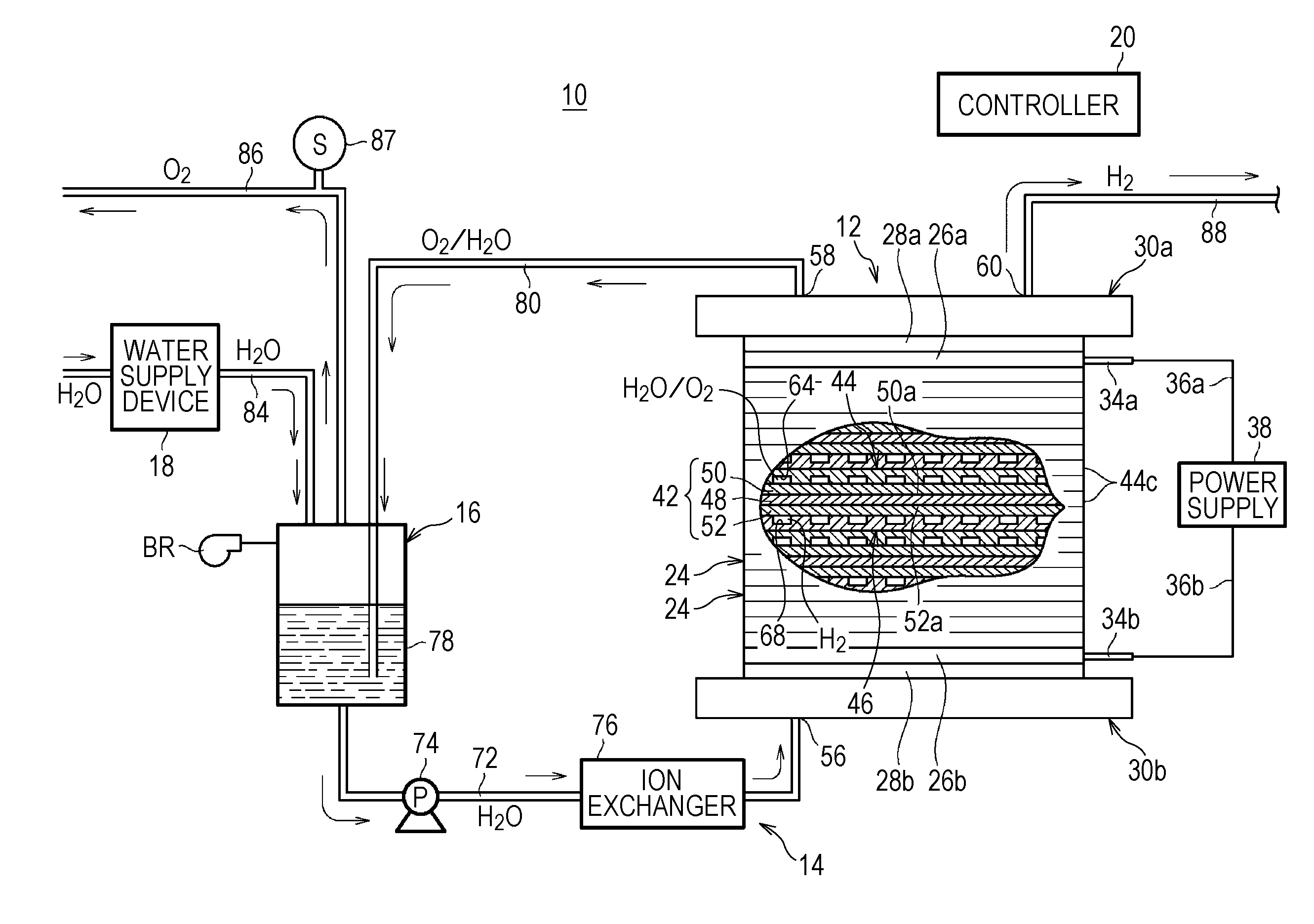
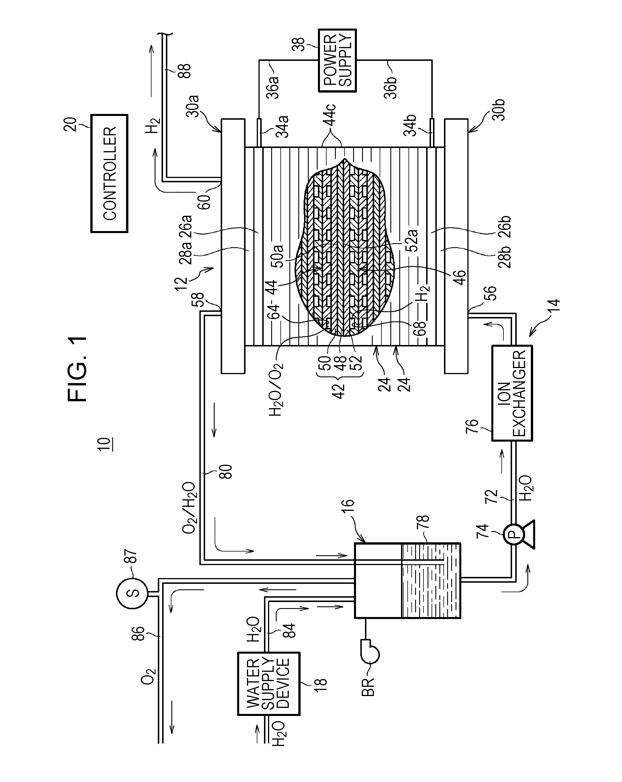
[0021]As shown in FIG. 1, a water electrolysis system 10 to which an operating method according to the present invention is applied includes a water electrolysis apparatus 12 which generates oxygen and high-pressure hydrogen (hydrogen under higher pressure than normal pressure) by electrolysis of water (pure water), a water circulation apparatus 14 which circulates the water in the water electrolysis apparatus 12, a gas-liquid separation apparatus 16 which separates the oxygen and hydrogen (gas components) discharged from the water electrolysis apparatus 12 from water in the water circulation apparatus 14 and stores the water, a water supply device 18 which supplies pure water produced from commercial water to the gas-liquid separation apparatus 16, and a controller (control section) 20.

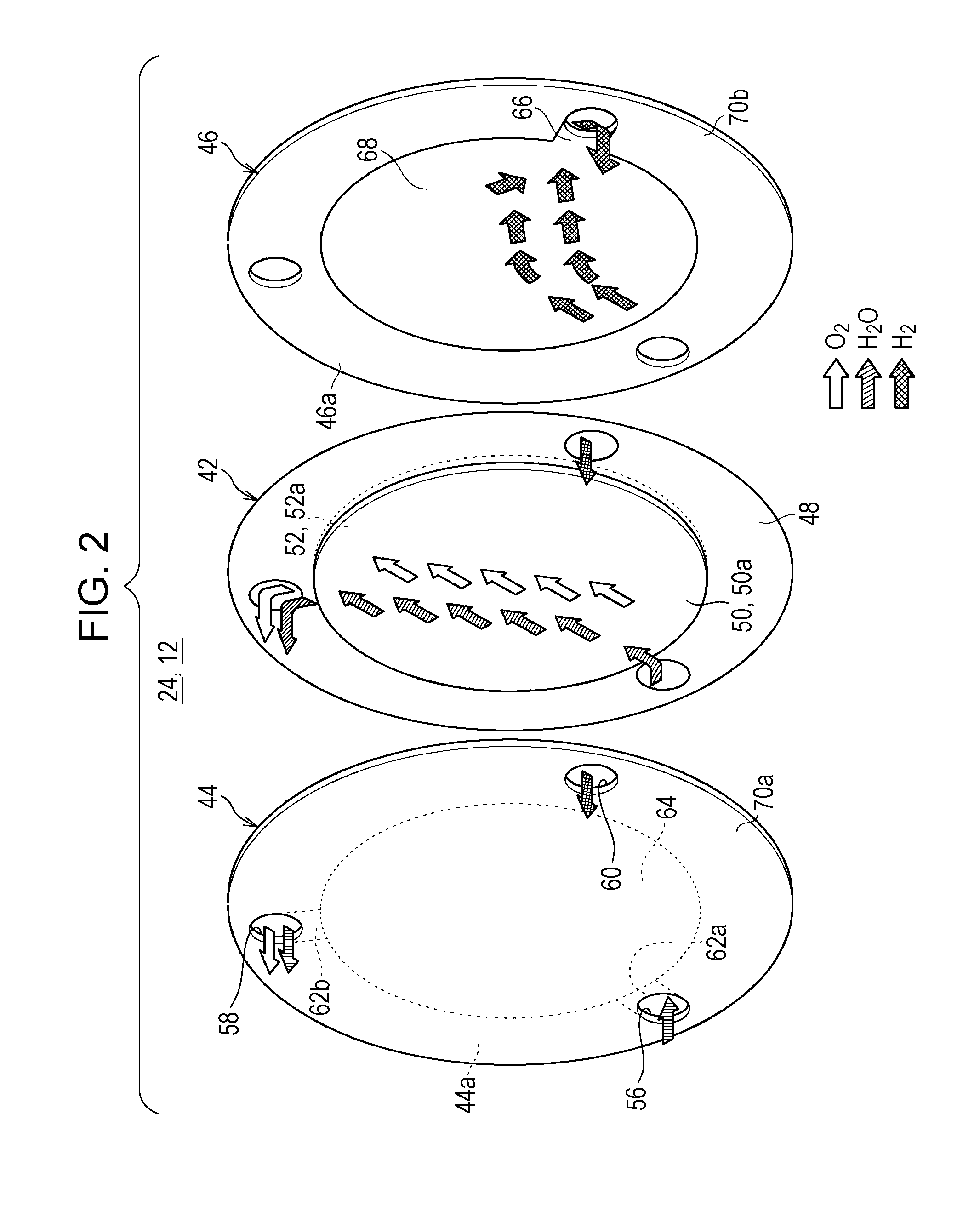
[0022]The water electrolysis apparatus 12 includes a stack of a plurality of unit cells 24. In addition, a terminal plate 26a, an insulating plate 28a, and an end plate 30a are disposed at an end in ...

second embodiment

[0051]In the second embodiment, a control map for driving the circulating pump 74 which constitutes the water circulation apparatus 14 is previously stored in the controller 20. The control map is based on a relation between the concentration of hydrogen remaining on the first flow passage 64 side and the operating time of the water circulation apparatus 14 after the water electrolysis apparatus 12 is stopped or based on a relation between the concentration of hydrogen remaining on the first flow passage 64 side and the revolution speed of the circulating pump 74 constituting the water circulation apparatus 14.

[0052]Therefore, processes from the system power supply is turned on (Step S21) to Step S29 are the same as Step S1 to Step S9 of the first embodiment. Further, after the release of pressure is completed (“YES” in Step S29), the operation proceeds to Step S30, and it is determined whether or not control based on the control map stored in the controlled 20 is completed.

[0053]Wh...


PUM

PropertyMeasurementUnit
porosityaaaaaaaaaa
porosityaaaaaaaaaa
pressureaaaaaaaaaa

Abstract

A method for operating a water electrolysis system includes determining whether or not a water electrolysis apparatus is shut down. The water electrolysis system includes the water electrolysis apparatus, a water circulation apparatus, and a gas-liquid separation apparatus. The water electrolysis apparatus includes power feeders provided on an anode side and a cathode side of an electrolyte membrane. The water electrolysis apparatus generates oxygen on the anode side and generates hydrogen on the cathode side at a higher pressure than a pressure of the oxygen by electrolysis of water. Pressure on the cathode side is released when it is determined that the water electrolysis apparatus is shut down. The water circulation apparatus is operated until a concentration of hydrogen remaining on the anode side is a specified value or less under a condition in which a release of pressure on the cathode side is completed.

Description

CROSS-REFERENCE TO RELATED APPLICATIONS[0001]The present application claims priority under 35 U.S.C. §119 to Japanese Patent Application No. 2010-012704 filed in the Japan Patent Office on Jan. 25, 2010, entitled “Method for Operating Water Electrolysis System”. The contents of this application are incorporated herein by reference in their entirety.BACKGROUND OF THE INVENTION[0002]1. Field of the Invention[0003]The present invention relates to a method for operating a water electrolysis system.[0004]2. Description of the Related Art[0005]For example, a solid polymer electrolyte fuel cell generates direct-current electric energy by supplying a fuel gas (gas mainly containing hydrogen, for example, hydrogen gas) to the anode-side electrode and an oxidizer gas (gas mainly containing oxygen, for example, air) to the cathode-side electrode.[0006]In order to produce hydrogen gas as the fuel gas, a water electrolysis apparatus is generally used. The water electrolysis apparatus uses a soli...

Claims


Application Information

Patent Timeline
Patent Type & Authority Applications(United States)
IPC IPC(8): C25B15/02C25B1/12
CPCC25B1/12Y02E60/366C25B15/02C25B1/04C25B9/05Y02E60/36
Inventor KURASHINA, DAISUKETARUYA, KENJITAKEUCHI, JUN
Owner HONDA MOTOR CO LTD
Why Eureka
Try Eureka