Screen panel center retainer system

Active Publication Date: 2011-07-28
CONN WELD IND
View PDF12 Cites 6 Cited by
  • Summary
  • Abstract
  • Description
  • Claims
  • Application Information

AI Technical Summary

Benefits of technology

[0018]Yet a further object of the present invention is to provide a screen panel center retainer system which provides increased open screen area.
[0019]Even still another object of the present invention is to provide a screen panel center retainer system which is easy to use and is cost effective.
[0020]An even further object of the present invention is to provide a screen panel center retainer sy

Problems solved by technology

However, each has its individual limitations which have made each system less than suitable for use in all equipment, regardless of manufacturer and configuration.
U.S. Pat. No. 6,964,341 have been found somewhat difficult to use and have required the provision of screen panel edge strips that have had to be field-installed on the replacement screen panels.
The abutment and alignment of these screen panel edge strips has been somewhat difficult to obtain in the field.
This has increased the time that is required to both initially install the prior systems and to then replace worn screen panels with replacement screen panels.
When a machine, which is operating in an industrial setting, must be taken out of service for repair or replacement of essential elements, that is a loss of that machine's production capac

Method used


Image

  • Screen panel center retainer system
  • Screen panel center retainer system
  • Screen panel center retainer system

Examples


Embodiment Construction

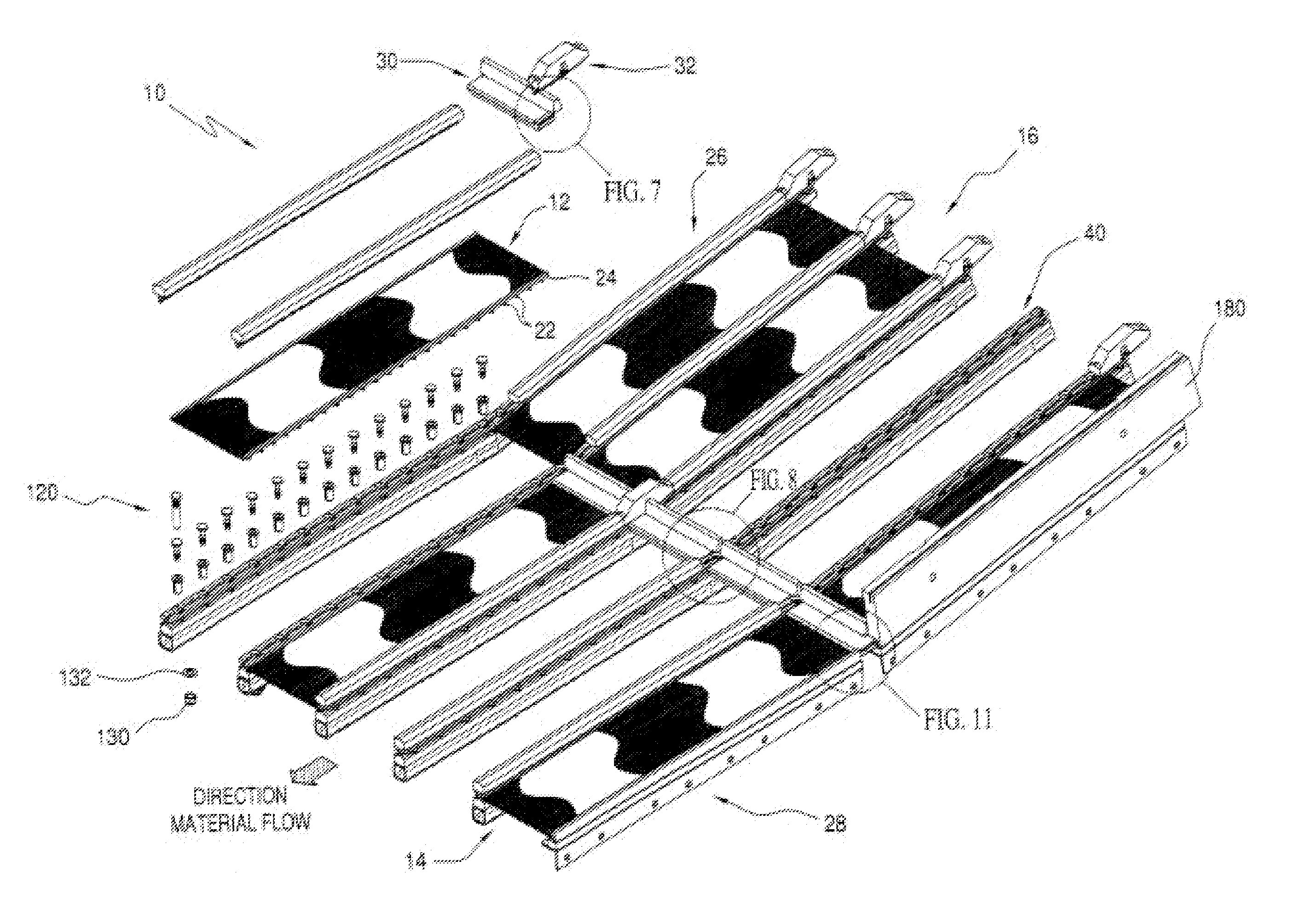
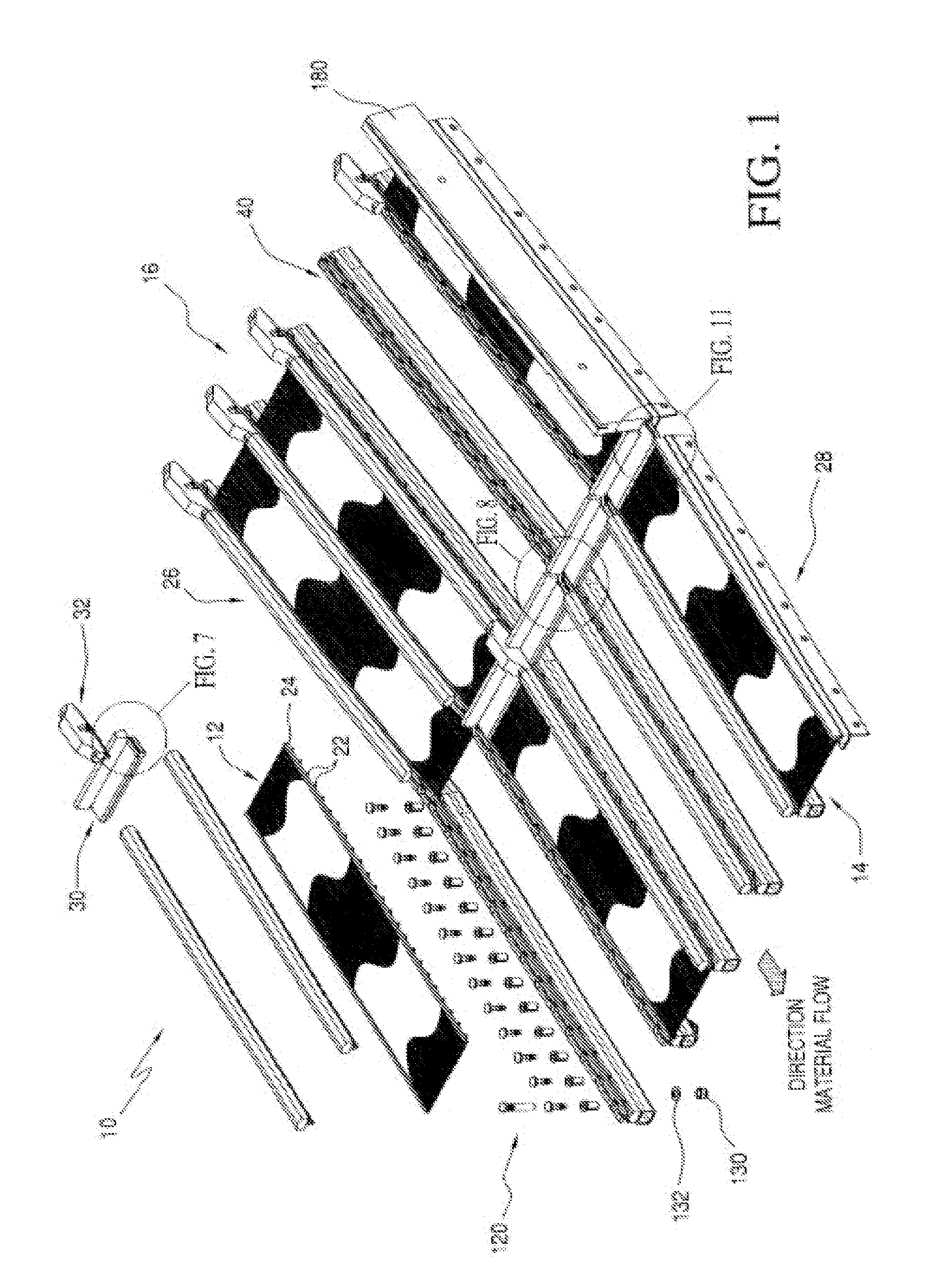
[0052]Referring initially to FIG. 1, there may be seen, generally at 10, a first preferred embodiment of a screen panel center retainer system in accordance with the present invention. Screen panel center retainer system 10, as depicted in FIG. 1, is usable to secure a plurality of screen panels, each identified generally at 12, in place on screen stringer rails, generally at 14 of a vibrating separatory machine, generally at 16. It is to be understood that the vibrating separatory machine, depicted generally at 16 in FIG. 1 is not, a complete depiction of such a machine. Vibrating separatory machines are generally well-known in the art and themselves do not form a part of the present invention. The assignee of this patent application Conn-Weld Industries of Princeton, W. Va., is the manufacturer of such vibrating separatory equipment. However, there are also other manufacturers of generally similar equipment. Only as much of a Conn-Weld Industries vibrating separatory machine, as i...


PUM


Abstract

A screen panel center retainer system for a vibrating separatory machine utilizes a center retainer that is provided with a retainer base which is adapted to be secured to screen stringer rails of a vibrating separatory machine. A pair of retainer channel legs form an upper portion of the center retainer and have screen panel edge receiving slots. A locking strip, having a wedging tongue, is used in conjunction with the center retainer. The wedging tongue is insertable into the channel on the center retainer which is defined by the two retainer channel legs. Flow control dams and cross dam retainers are used in conjunction with, and in addition to the center retainers and locking strips. The cross dam retainers are provided with locking strip end receiving pockets, to compensate for changes in the length of the locking strips. The screen panel center retainer system is configured to provide a functional, universal installation of screen panels on vibrating separating machines.

Description

CROSS-REFERENCE TO RELATED APPLICATIONS[0001]This application is a continuation-in-part of prior application Ser. No. 12 / 216,334, filed Jul. 11,26.08, the disclosures of which are expressly incorporated herein by reference.FIELD OF THE INVENTION[0002]The present invention is directed generally to a screen panel center retainer system. More particularly, the present invention is directed to a center retainer system for use in retaining screen panels on a vibrating separatory device. Most specifically, the present invention is directed to a screen panel retainer system that is usable to releasably mount screen panels on screen stringer rails of vibrating separatory machines. A center retainer is secured to each of the screen stringer rails of a generally conventional vibrating separatory machine. The center retainer is attachable to the screen stringer rails using expansion sleeves and expansion pins, or bolts. A lock strip has a wedge tongue that is configured to be receivable in a c...

Claims


Application Information

Patent Timeline
IPC IPC(8): B07B1/46
CPCB07B1/4645
Inventor LANE, TRACY LEONARDBACHO, FRANK J.
Owner CONN WELD IND
Why Eureka
Try Eureka