Screen panel center retainer system

a screen panel and center retainer technology, applied in the field of screen panel center retainer system, can solve the problems of difficult alignment of the abutment and the edge strip of the screen panel, less than suitable for use in all equipment, and difficulty in obtaining the abutment and alignment, so as to increase the open screen area, cost-effective, and convenient use

Active Publication Date: 2011-05-24
CONN WELD IND
View PDF13 Cites 16 Cited by
  • Summary
  • Abstract
  • Description
  • Claims
  • Application Information

AI Technical Summary

Benefits of technology

[0015]Still another object of the present invention is to provide a screen panel center retainer system which does not require the modification of screen panels.
[0016]Yet a further object of the present invention is to provide a screen panel center retainer system which provides increased open screen area.
[0017]Even still another object of the present invention is to provide a screen panel center retainer system which is easy to use and is cost effective.

Problems solved by technology

However, each has its individual limitations which have made each system less than suitable for use in all equipment, regardless of manufacturer and configuration.
Others, such as the system described in the Bacho et al. patent, U.S. Pat. No. 6,964,341 have been found somewhat difficult to use and have required the provision of screen panel edge strips that have had to be field-installed on the replacement screen panels.
The abutment and alignment of these screen panel edge strips has been somewhat difficult to obtain in the field.
This has increased the time that is required to both initially install the prior systems and to then replace worn screen panels with replacement screen panels.
When a machine, which is operating in an industrial setting, must be taken out of service for repair or replacement of essential elements, that is a loss of that machine's production capacity.
Several of the prior screen panel securement arrangements, in addition to their requirement of special screen panel edge strips, have required numerous parts and have been expensive to make and install.
As discussed above, when a production machine is taken out of service, money is lost.
While that reduction in available screen surface area may amount to only 5% of the total screen surface area, that is still 5% of the total screen surface area which is no longer available for accomplishing the machine's primary objective of separation of solids from a slurry.

Method used


Image

  • Screen panel center retainer system
  • Screen panel center retainer system
  • Screen panel center retainer system

Examples


Embodiment Construction

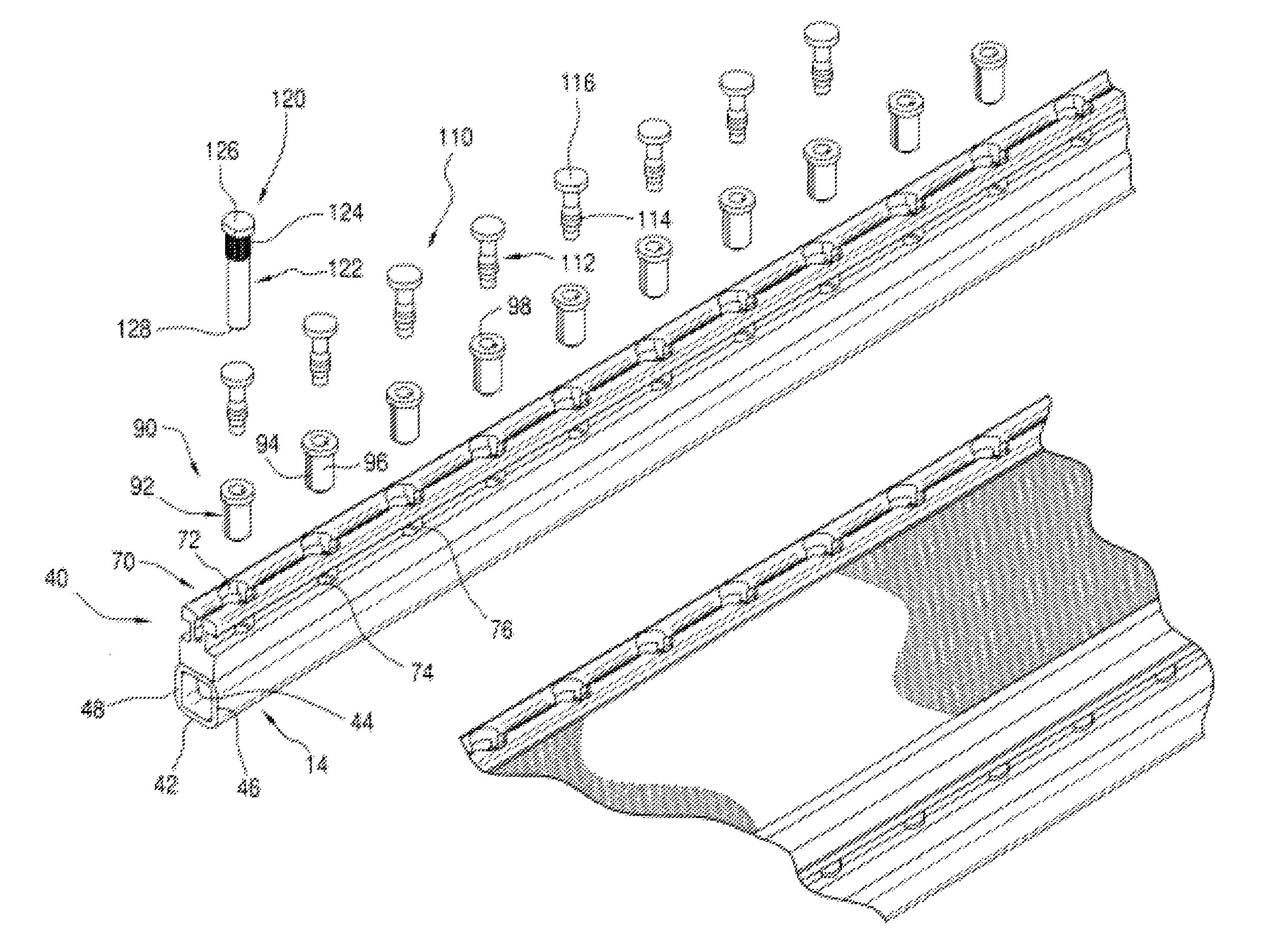
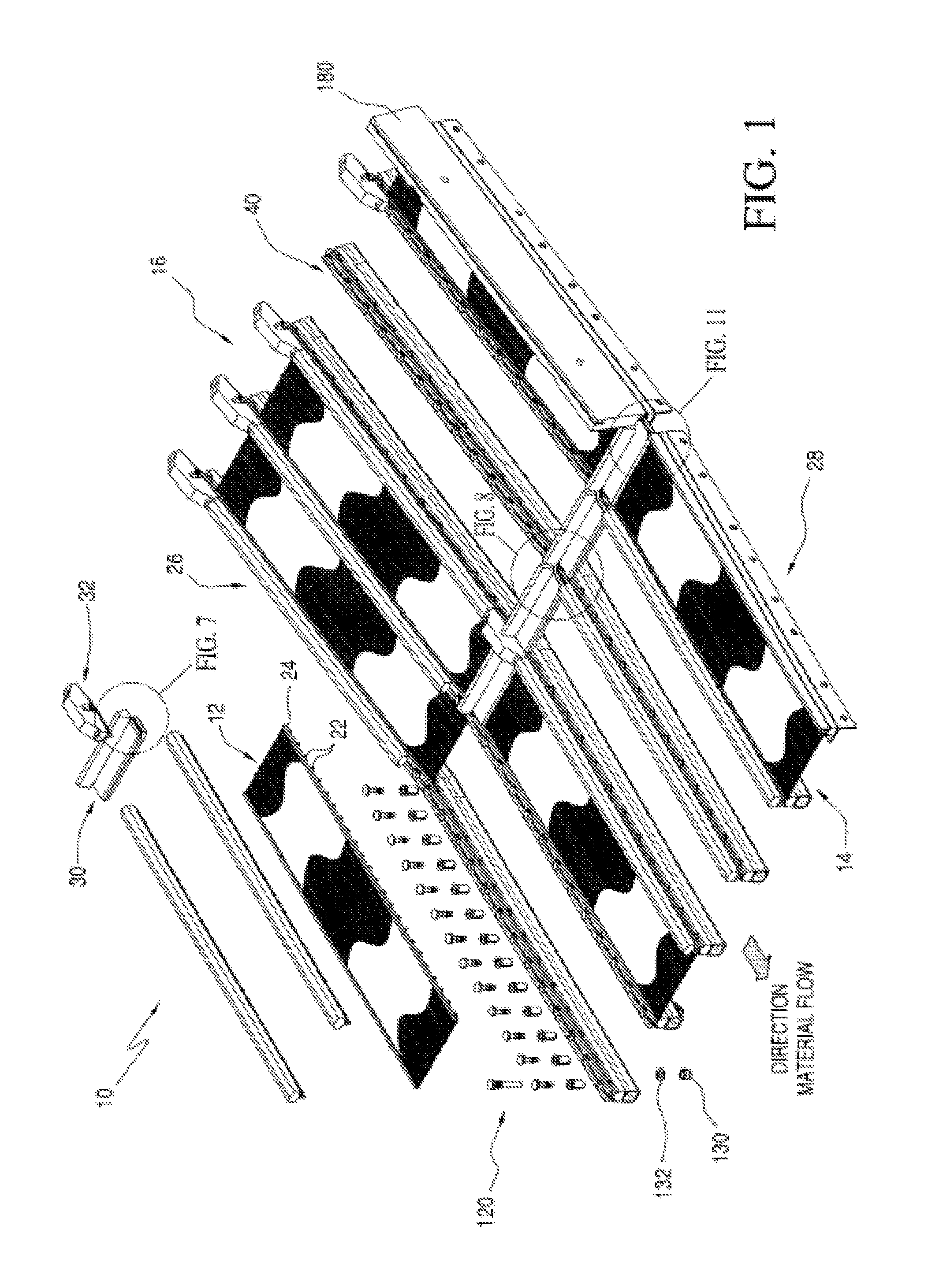
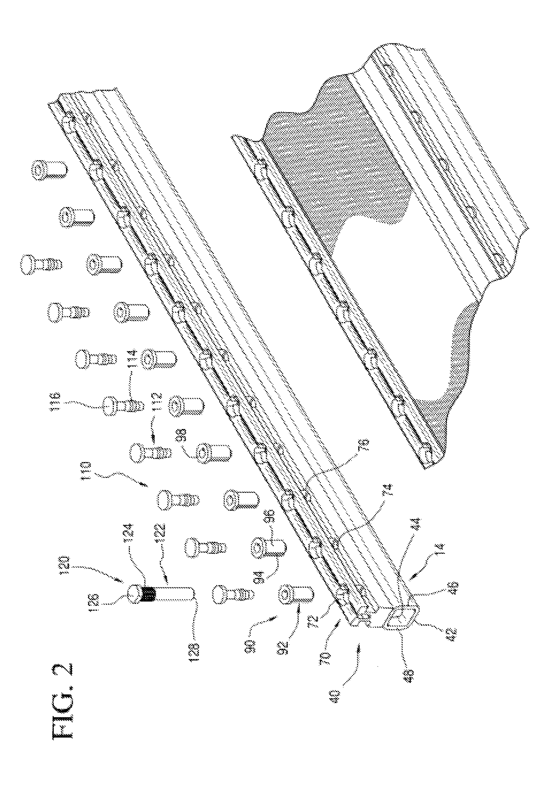
[0038]Referring initially to FIG. 1, there may be seen, generally at 10, a preferred embodiment of a screen panel center retainer system in accordance with the present invention. Screen panel center retainer system 10, as depicted in FIG. 1, is usable to secure a plurality of screen panels, each identified generally at 12, in place on screen stringer rails, generally at 14 of a vibrating separatory machine, generally at 16. It is to be understood that the vibrating separatory machine, depicted generally at 16 in FIG. 1 is not a complete depiction of such a machine. Vibrating separatory machines are generally well-known in the art and themselves do not form a part of the present invention. The assignee of this patent application, Conn-Weld Industries of Princeton, W. Va., is the manufacturer of such vibrating separatory equipment. However, there are also other manufacturers of generally similar equipment. Only as much of a Conn-Weld Industries vibrating separatory machine, as is requ...


PUM


Abstract

A screen panel center retainer system utilizes a center retainer that is provided with a retainer base which is adapted to be secured to screen stringer rails of a vibrating separatory machine. A pair of retainer channel legs form an upper portion of the center retainer and have screen panel edge receiving slots. A locking strip, having a wedging tongue, is used in conjunction with the center retainer. The wedging tongue is insertable into the channel on the center retainer which is defined by the two retainer channel legs. Flow control dams and cross dam retainers are used in conjunction with, and in addition to the center retainers and locking strips, to provide the complete installation of screen panels on the vibrating separating machine.

Description

FIELD OF THE INVENTION[0001]The present invention is directed generally to a screen panel center retainer system. More particularly, the present invention is directed to a center retainer system for use in retaining screen panels on a vibrating separatory device. Most specifically, the present invention is directed to a screen panel retainer system that is usable to releasably mount screen panels on screen stringer rails of vibrating separatory machines. A center retainer is secured to each of the screen stringer rails of a generally conventional vibrating separatory machine. The center retainer is attachable to the screen stringer rails using expansion sleeves and expansion pins, or bolts. A lock strip has a wedge tongue that is configured to be receivable in a cooperating central channel of the center retainer. Insertion of the wedge tongue into the center retainer channel acts to deflect channel walls apart and into engagement with screen tie rods and spacer bars on screen panels...

Claims


Application Information

Patent Timeline
Patent Type & Authority Patents(United States)
IPC IPC(8): B07B1/49
CPCB07B1/4645
Inventor LANE, TRACY LEONARDBACHO, FRANK J.
Owner CONN WELD IND
Why Eureka
Try Eureka