Methods and systems for binding a wireless control device to a welding power source

a wireless control and power supply technology, applied in the field of welding systems, can solve problems such as confusion and potential errors in setting the power supply for the desired welding operation, limit the reach of the control device, and limit the range of the control devi

Inactive Publication Date: 2011-07-28
ILLINOIS TOOL WORKS INC
View PDF45 Cites 61 Cited by
  • Summary
  • Abstract
  • Description
  • Claims
  • Application Information

AI Technical Summary

Benefits of technology

[0005]In an exemplary embodiment, a welding system includes a welding power source adapted to generate a welding power output for use in a welding operation and a wireless control device adapted to substantially exclusively control operation of the welding power source when the wireless control device is bound to the welding power source. The welding system also includes a receiver integrated with the welding power source and adapted to learn a first address specific to the receiver and the wireless control device pair to exclusively bind the welding power supply to the wireless control device during a learning mode and to clear the first address upon initiation of a second learning mode. The wireless control device is adapted to learn the first address specific to the receiver and the wireless control device pair to exclusively...

Problems solved by technology

Unfortunately, the welding environment is often cluttered with many cords, and the wired connection between the control device and the power source may introduce additional undesirable clutter and may limit the reach of the control device.
Unfortunately, since such devices no longer feature a wired connection to the...

Method used


Image

  • Methods and systems for binding a wireless control device to a welding power source
  • Methods and systems for binding a wireless control device to a welding power source
  • Methods and systems for binding a wireless control device to a welding power source

Examples


Embodiment Construction

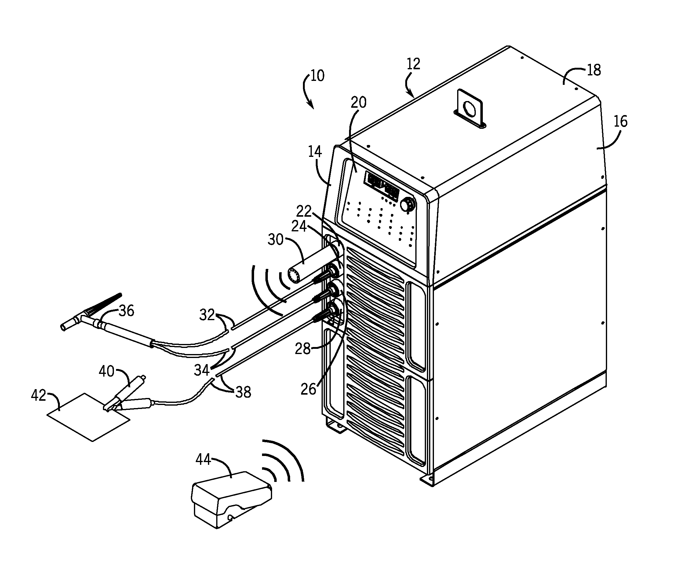
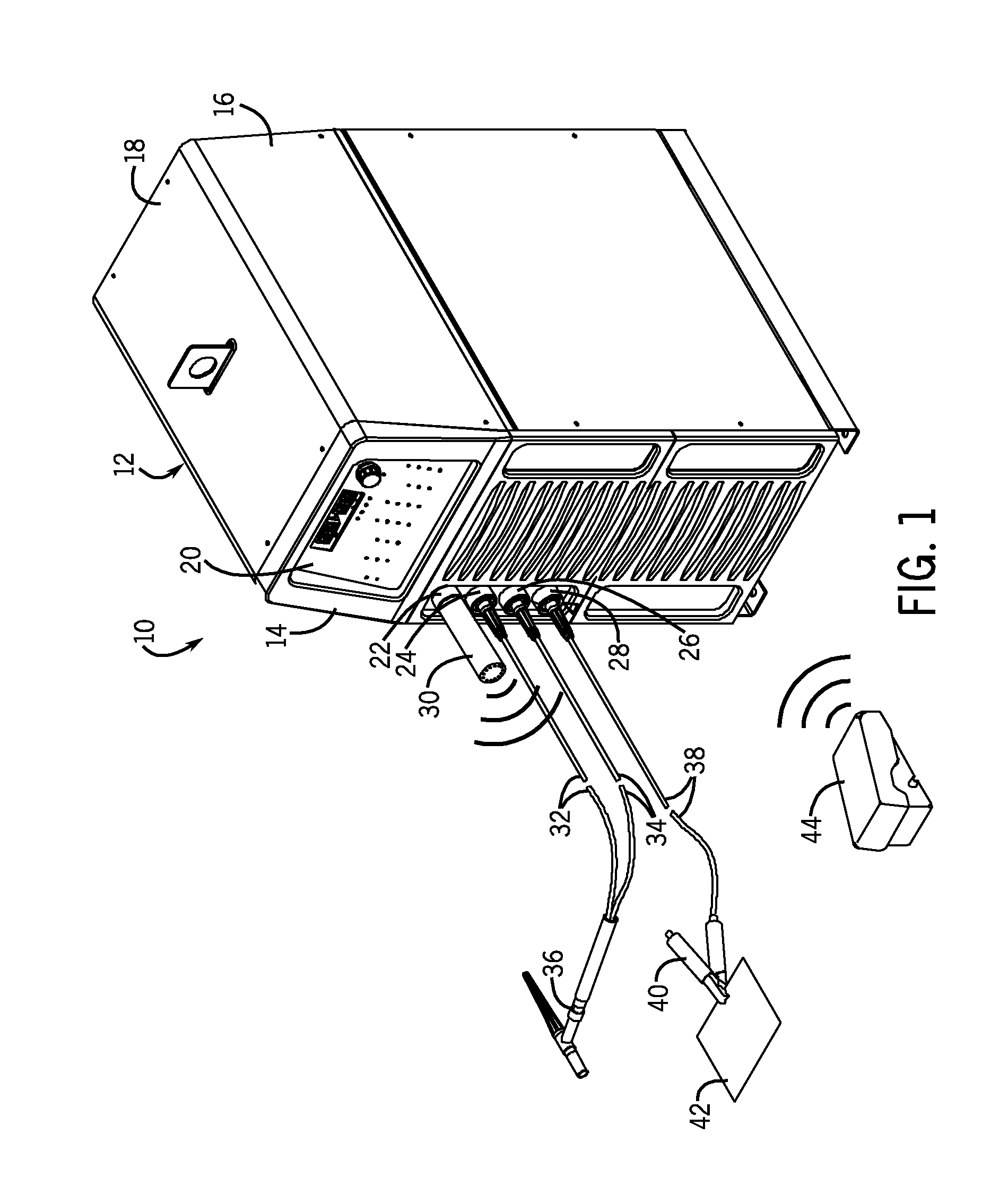
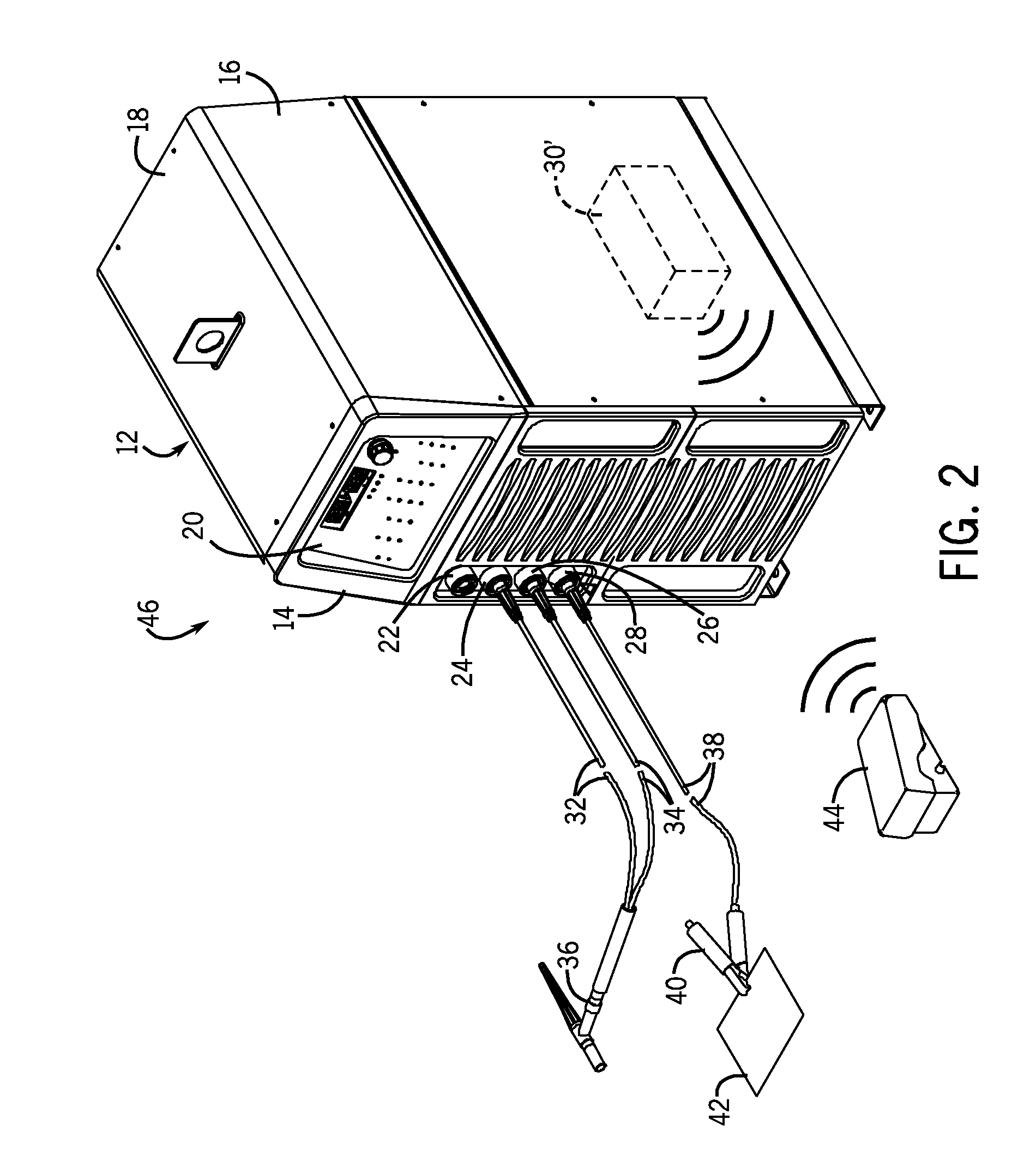
[0014]As described in detail below, embodiments of welding systems including a welding power source, a receiver associated with the welding power source, and a wireless control are provided. The wireless control may be bound to any of a variety of welding power sources and, when bound, the wireless control is configured to control operation of one or more parameters of the welding power source. Similarly, the welding power source may be bound to a variety of wireless control devices and, when bound, the welding power source is configured to be controlled by the wireless control device to which it is bound. Further, such a bind between a particular wireless control device and a given welding power source may occur when each device is placed in a learning mode and is located within a given distance threshold. For example, if a wireless control is located beyond a given distance threshold, the welding power source and / or the wireless control device may prevent initiation of the bindi...


PUM

PropertyMeasurementUnit
Poweraaaaaaaaaa
Distanceaaaaaaaaaa

Abstract

A welding system including a welding power source, a receiver, and a wireless control device are provided. The receiver is adapted to communicate information to and from the welding power source. The wireless control device and/or the receiver is adapted to learn a first address specific to the receiver and the wireless control device pair to exclusively bind the welding power source to the wireless control device during a learning mode. Such a binding may occur when the wireless control device is located a distance from the welding power source that is below a preset threshold. The wireless control device controls operation of the welding power source when the wireless control device is bound to the welding power source.

Description

CROSS REFERENCE TO RELATED APPLICATIONS[0001]This application is a Non-Provisional Patent Application of U.S. Provisional Patent Application No. 61 / 298,341 entitled “Method for Programming a Wireless Welding System”, filed Jan. 26, 2010, which is herein incorporated by reference.BACKGROUND[0002]The invention relates generally to welding systems and, more particularly, to the binding of wireless controls to welding power supplies.[0003]Welding is a process that has become ubiquitous in various industries for a variety of types of applications. For example, welding is often performed in applications such as shipbuilding, aircraft repair, construction, and so forth. During such welding processes, a variety of control devices are often provided to enable an operator to control one or more parameters of the welding operation. For example, foot and hand activated controls may be provided such that the operator may alter the amperage, voltage, or any other desirable parameter of the weldin...

Claims


Application Information

Patent Timeline
IPC IPC(8): B23K11/24
CPCH04W8/26B23K9/1006
Inventor SCHNEIDER, JOSEPH C.
Owner ILLINOIS TOOL WORKS INC
Why Eureka
Try Eureka