

Radiographic imaging device and radiographic imaging apparatus
a radiographic imaging and imaging device technology, applied in the field of radiographic imaging devices, can solve the problems of reducing the pixel size the inability to dispose of the first conversion element continuously, and the inability to detect the image data. , to achieve the effect of good radiographic image quality and good precision of radiation irradiation amount detection
- Summary
- Abstract
- Description
- Claims
- Application Information
AI Technical Summary
Benefits of technology
Problems solved by technology
Method used
Image

Examples
first exemplary embodiment
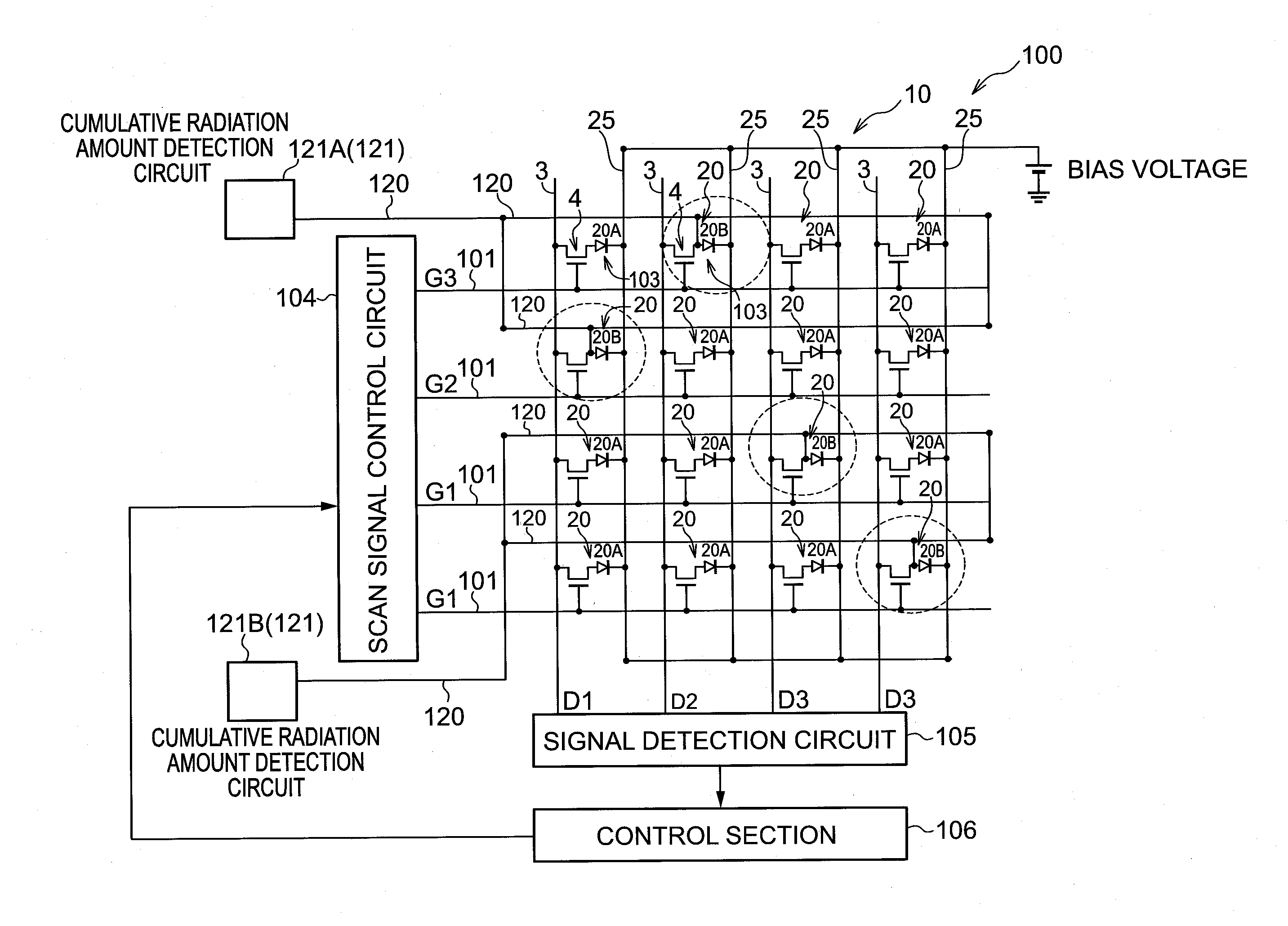
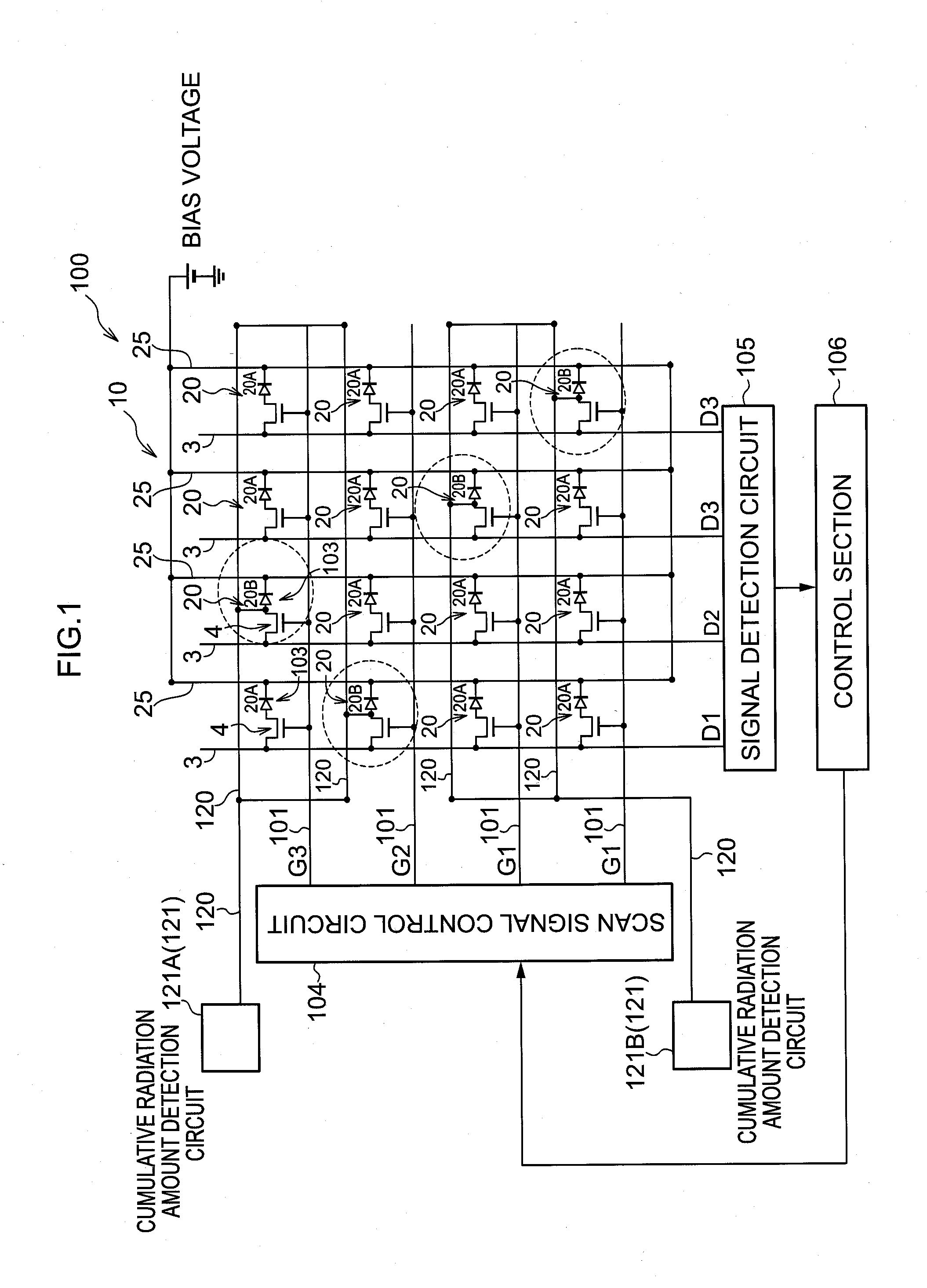
[0049]FIG. 1 shows an overall configuration of a radiographic imaging apparatus 100 in which the radiographic imaging device 10 according to a first exemplary embodiment is employed.
[0050]As shown in FIG. 1, the radiographic imaging apparatus 100 according to the present exemplary embodiment includes the radiographic imaging device 10 of indirect-conversion-type. Note that a scintillator that converts radiation into light is omitted in the drawing.
[0051]The radiographic imaging device 10 is provided with plural pixels 20 each configured to include a sensor portion 103 and a TFT switch 4. The sensor portion 103 receives light, generates charge, and accumulates the generated charge. The TFT switch 4 reads out the charge that has accumulated in the sensor portion 103. In the present exemplary embodiment, the sensor section 103 generates charge by illumination with light that has been converted by the scintillator. The TFT switch 4 corresponds to a switch element of the present inventio...
second exemplary embodiment
[0108]Explanation now follows regarding a second exemplary embodiment.
[0109]FIG. 9 shows an overall configuration of a radiographic imaging apparatus 100 employing a radiographic imaging device 10 according to a second exemplary embodiment. Note that since the configuration of the radiographic imaging device 10 according to the second exemplary embodiment is similar to that of the first exemplary embodiment (see FIG. 2 to FIG. 4), further explanation thereof is omitted.
[0110]The radiographic imaging apparatus 100 according to the present exemplary embodiment is equipped with an X-ray detection circuit 130.
[0111]The radiation detection lines 120 provided to the radiographic imaging device 10 are connected to the X-ray detection circuit 130. The X-ray detection circuit 130 amplifies the electrical signal flowing in the radiation detection lines 120 with an amplification circuit. The X-ray detection circuit 130 operates under control from the control section 106, amplifies the electric...
third exemplary embodiment
[0128]Explanation now follows regarding a third exemplary embodiment. The configuration of a radiographic imaging device 10 according to the third exemplary embodiment is similar to that of the first exemplary embodiment (see FIG. 2 to FIG. 4). Also, the operation of the configuration of the radiographic imaging apparatus 100 according to the third exemplary embodiment and operation during radiographic imaging are also substantially similar to that of the second exemplary embodiment (see FIG. 9 and FIG. 10). Accordingly, further explanation thereof is omitted.
[0129]FIG. 13 shows a timing chart showing operation during radiographic imaging with the radiographic imaging apparatus 100 according to the third exemplary embodiment.
[0130]The control section 106 transitions to the radiation detection waiting state when notified to transition to imaging mode. Then, the control section 106 controls the scan signal control circuit 104 to output OFF signals from the scan signal control circuit ...
PUM
 Abstract
Description
Claims
Application Information