Roof assembly and method of mounting a sieve member

a technology of sieve member and sieve body, which is applied in the direction of roof, superstructure subunit, transportation and packaging, etc., can solve the problem that the debris cannot reach the drainage member, and achieve the effect of reducing the risk and facilitating removal

Inactive Publication Date: 2011-07-28
INALFA ROOF SYST GROUP
View PDF12 Cites 2 Cited by
  • Summary
  • Abstract
  • Description
  • Claims
  • Application Information

AI Technical Summary

Benefits of technology

[0007]Due to this sieve member, the debris cannot reach the drainage member. The shape of the sieve member can be easily chosen such that water can still seep through even if debris have accumulated in front of the sieve, so that a total blockage of the drain will not occur.
[0008]In a first embodiment, the sieve member is mounted to said longitudinal guide, and in particularly mainly in said drain channel. In this way, the dirt and leaves will remain in the drain channel where it is relatively easy to collect and remove the dirt and / or leaves. This embodiment is also suited for mounting the sieve after the roof assembly has been built in the vehicle, as the drain channel can easily be reached from inside or outside the vehicle.
[0010]In this embodiment, the water may seep through the bottom of the sieve member over a relatively great length, thereby further reducing the risk of blocking the sieve member.
[0011]In another embodiment, the sieve member is slidably mounted to said longitudinal guide and is operatively connected to said operating mechanism, said sieve member being constructed as a scraper. In this embodiment, the sieve member will follow movements of the closure operating mechanism, and will scrape any collected dirt and leaves forwardly, which makes removal easier.
[0013]In another embodiment, the water drainage member is provided with a drain pipe for mounting the drainage hose, the sieve member having a mounting part fixed within the drain pipe and a sieve part protruding upstream from the mounting part. This leads to a very simple sieve member.
[0019]By using this method, it is not necessary to demount or dismantle a roof assembly for the vehicle in order to be able to install the sieve assembly in existing roof assemblies.

Problems solved by technology

Due to this sieve member, the debris cannot reach the drainage member.

Method used


Image

  • Roof assembly and method of mounting a sieve member
  • Roof assembly and method of mounting a sieve member
  • Roof assembly and method of mounting a sieve member

Examples


Embodiment Construction

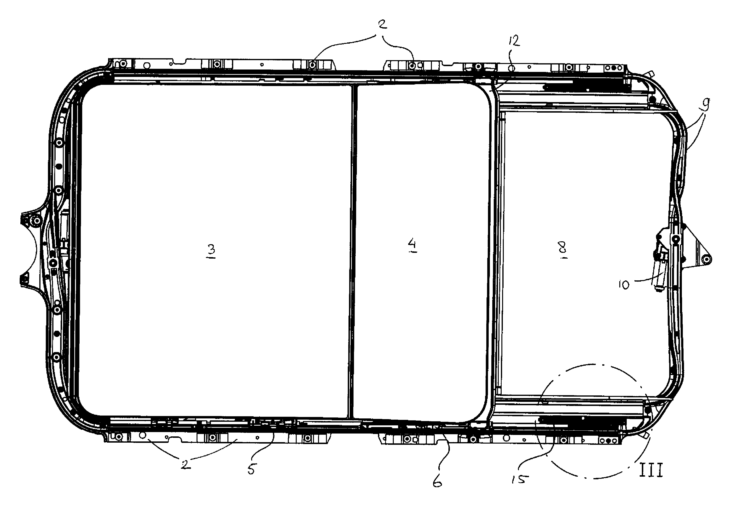
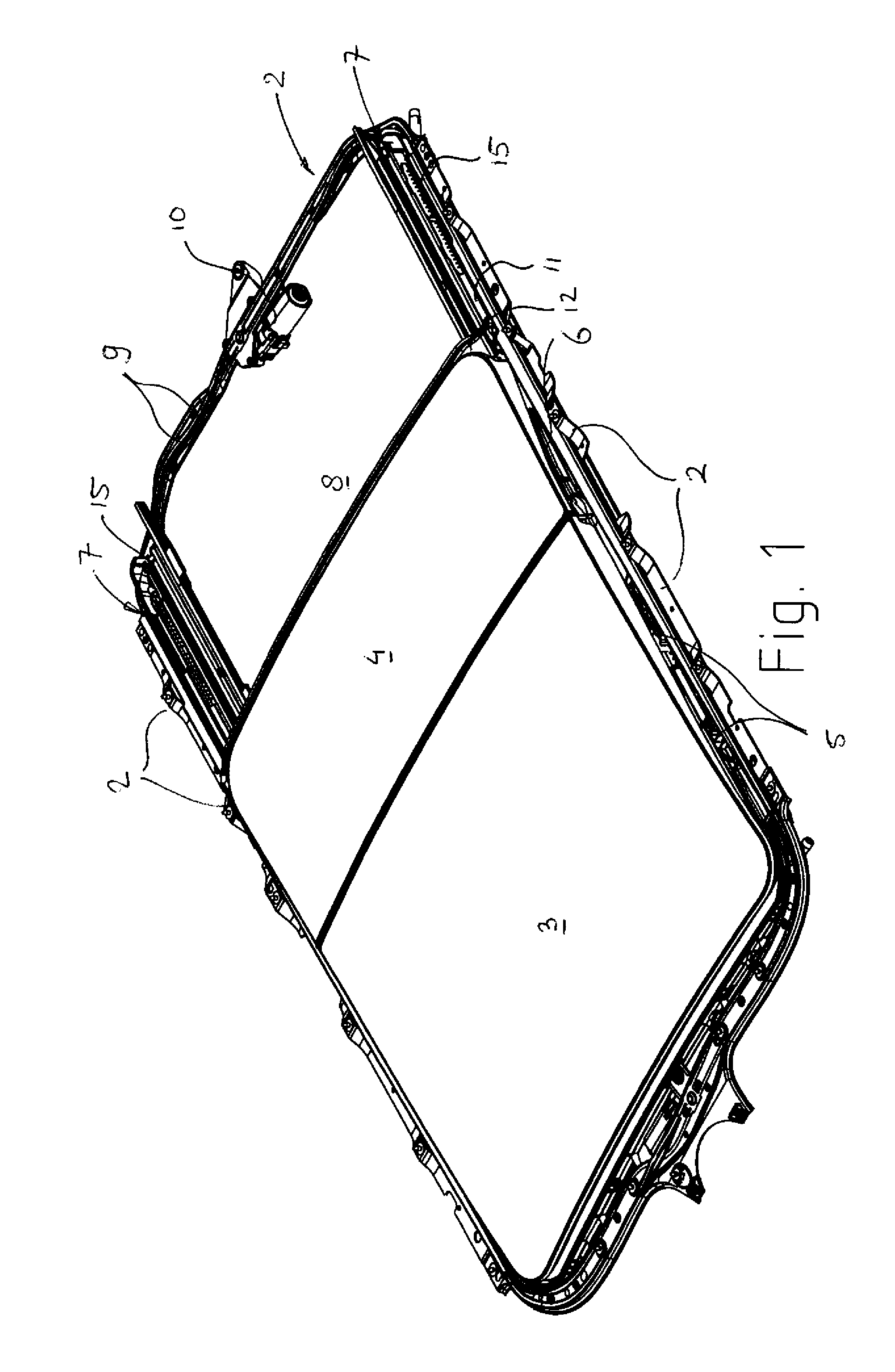
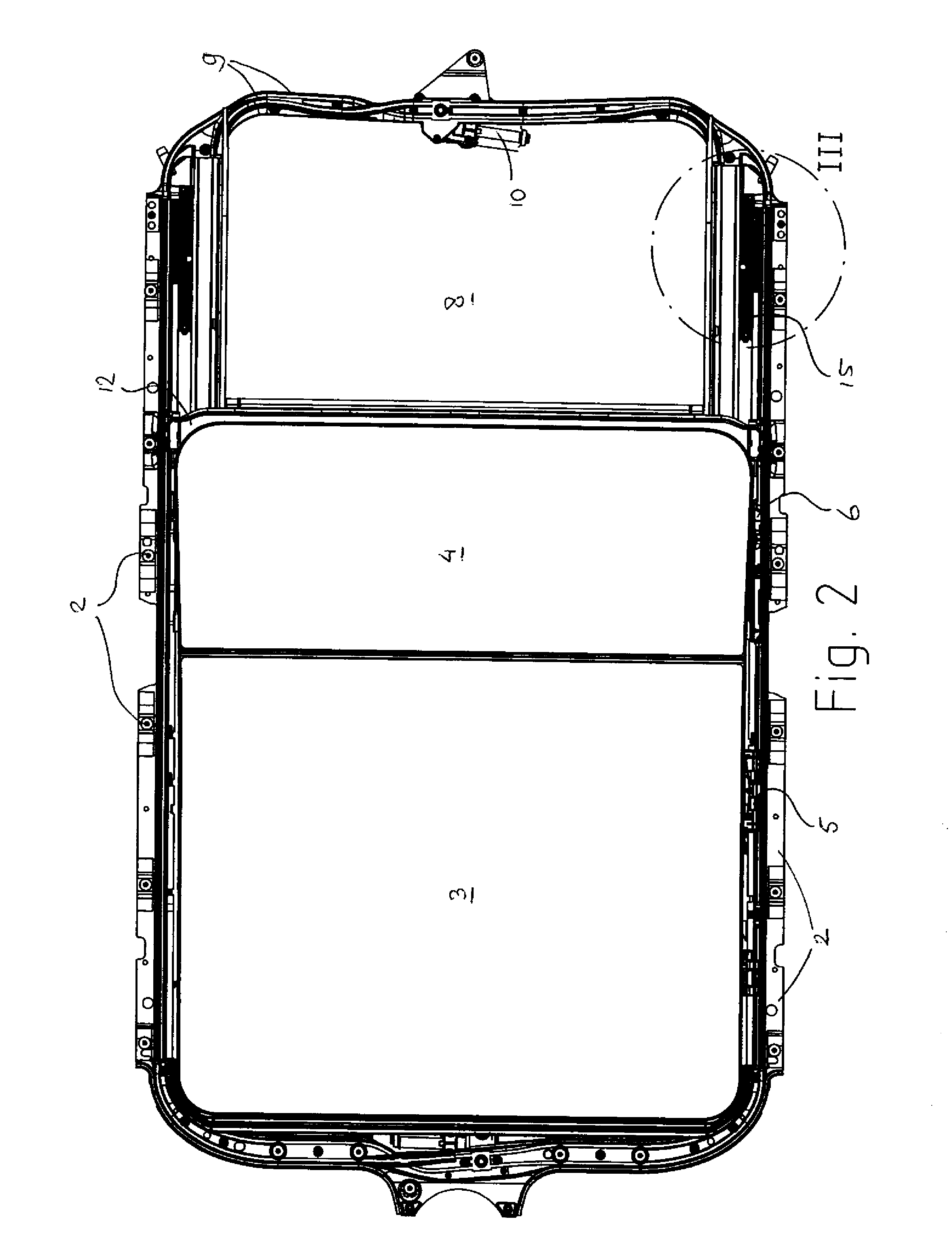
[0035]FIGS. 1 and 2 show an embodiment of a roof assembly for a vehicle, in particular a passenger car. The roof assembly comprises a stationary part, here in the form of a frame 1, having attachment elements 2 to fix the frame 1 to the bodywork of the vehicle. The roof assembly further comprises a closure in the form of one or more closure members, here in the form of a front glass panel 3 and a rear glass panel 4. Of course all kinds of other closure arrangements as known in the prior art are conceivable, such as slats, folding covers and the like. The panels 3, 4 can be positioned in a closed position in which they separately or jointly close an opening in the fixed roof of the vehicle. This fixed roof may be either part of the roof assembly or may be a part of the vehicle in which the roof assembly is mounted. The panels 3, 4 can be fixed, but in this embodiment they are both movable from their closed position in the roof opening to an open position in which they at least partly...


PUM

PropertyMeasurementUnit
shapeaaaaaaaaaa
lengthaaaaaaaaaa
flexibleaaaaaaaaaa

Abstract

Aspects of the invention relate to a roof assembly for a vehicle having a roof opening in its fixed roof. It comprises a stationary part having longitudinal guides positioned on either side of the roof opening. A closure is movable at least between a closed position closing the roof opening and an open position in which the closure is at least partly opening the roof opening. A closure operating mechanism is provided for opening and closing the closure, and is sliding in said longitudinal guides when opening and closing the closure. The longitudinal guides each comprise at least a drain channel and a water drainage member for draining water from said longitudinal drain channel to a water drainage hose. Each water drainage member communicates with the respective drain channel on one end, and connects to the corresponding water drainage hose on its opposite end to form a drain. A sieve member for catching debris but allowing water to run through is provided in the drain upstream of said water drainage member.

Description

BACKGROUND[0001]The discussion below is merely provided for general background information and is not intended to be used as an aid in determining the scope of the claimed subject matter.[0002]Aspects of the invention relate to a roof assembly for a vehicle having a roof opening in its fixed roof, comprising a stationary part having longitudinal guides positioned on either side of the roof opening, a closure movable at least between a closed position closing the roof opening and an open position in which the closure is at least partly opening the roof opening, a closure operating mechanism for opening and closing said closure, said operating mechanism sliding in said longitudinal guides when opening and closing said closure, and wherein said longitudinal guides each comprise at least a drain channel and a water drainage member for draining water from said drain channel to a water drainage hose, each water drainage member communicating with the respective drain channel on one end, an...

Claims


Application Information

Patent Timeline
Patent Type & Authority Applications(United States)
IPC IPC(8): B60R13/07B23P17/04
CPCB60J7/0084Y10T29/49826B60J7/043
Inventor BOERSMA, EGBERTRELOUW, MICHAEL CORNELIS ANTHONIUSKOK, DANNY WILHELMUS ARENDVERBEEK, LEONARDUS GERARDUS MARIA
Owner INALFA ROOF SYST GROUP
Why Eureka
Try Eureka