Air cleaner; aerosol separator; and method

a technology of air cleaner and separator, which is applied in the direction of separation process, filtration separation, combustion-air/fuel-air treatment, etc., can solve the problems of carrying substantial amounts of fine contaminant, and achieve the effect of convenient and advantageous assembly

Inactive Publication Date: 2001-02-13
DONALDSON CO INC
View PDF99 Cites 181 Cited by
  • Summary
  • Abstract
  • Description
  • Claims
  • Application Information

AI Technical Summary

Benefits of technology

An arrangement for separating a hydrophobic liquid phase from a gaseous stream (sometimes referred to herein as a coalescer / separator arrangement) is provided. In operation, a contaminated gas flow is directed into the coalescer / separator arrangement. Within the arrangement, the fine oil phase or aerosol phase (i.e., hydrophobic phase) coalesces. The arrangement is constructed so that as the hydrophobic phase coalesces into droplets, it will drain as a liquid such that it can readily be collected and removed from the system. With preferred arrangements as described herein below, the coalescer or coalescer / separator, especially with the oil phase in part loaded thereon, operates as a prefilter for carbon contaminant carried in the gas stream. In preferred arrangements, the coalescer / separator arrangement is constructed with a removable media component for ease of cleaning or regeneration. In some preferred systems, at least a single downstream (or second) filter or polish filter is provided.
This axial force will translate into: (a) an axial force between the planar region 118 of the centering construction 90 of filter element 62 and the axial seal member 138 of the second stage air cleaner 57; and (b) an axial force between the inner surface 278 of the housing 50 and the axial seal member 232 on the end cap 226. Eventually, the axial forces will cause enough compression of the axial seal member 138 with the centering construction 90 and the axial seal member 232 with the inner surface 278 of the housing 50, that an axial seal 274 will be formed between the centering construction 90 and the end cap 140 of the second stage air cleaner 57; and an axial seal 280 will be formed between the inner surface 278 of the housing 50 and the end cap 226 of the second stage air cleaner 57. The axial seals 274 and 280 will prevent an unintended amount of air flow from bypassing the media pack 64 and the media pack 212 of the second stage air cleaner 57 and proceed directly to the clean air chamber 68 and 101, during normal operation.

Problems solved by technology

In addition, such gas streams also carry substantial amounts of fine contaminant, such as carbon contaminants.

Method used


Image

  • Air cleaner; aerosol separator; and method
  • Air cleaner; aerosol separator; and method
  • Air cleaner; aerosol separator; and method

Examples


Embodiment Construction

In this section, examples are provided of usable materials. The particular choice for any given material will vary, depending on the filtering application. In other words, the particular material selected for the systems usable herein will be decided upon by the system designer based on the system requirements. A variety of materials are possible. The following section provides examples of materials that have been found to be suitable.

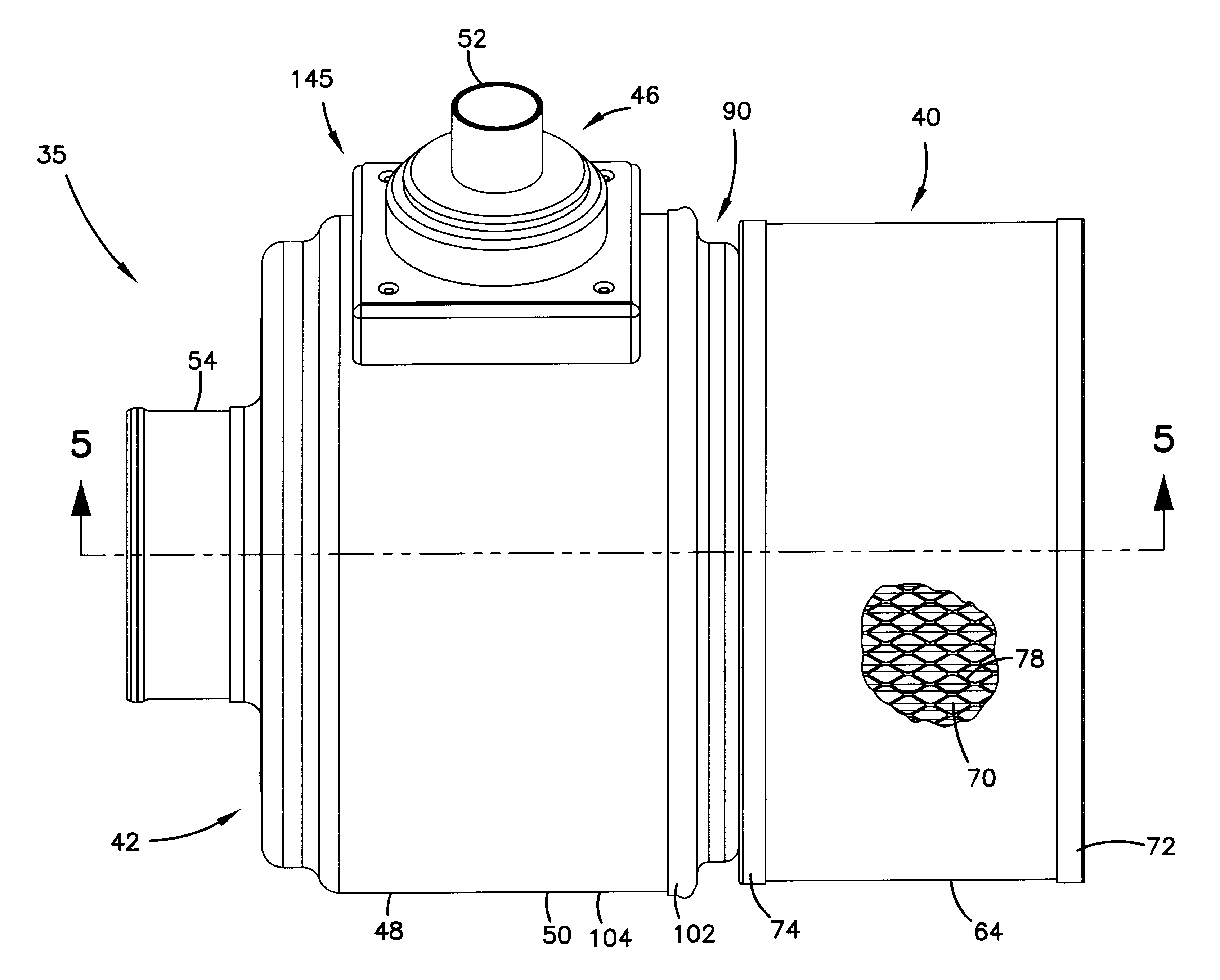
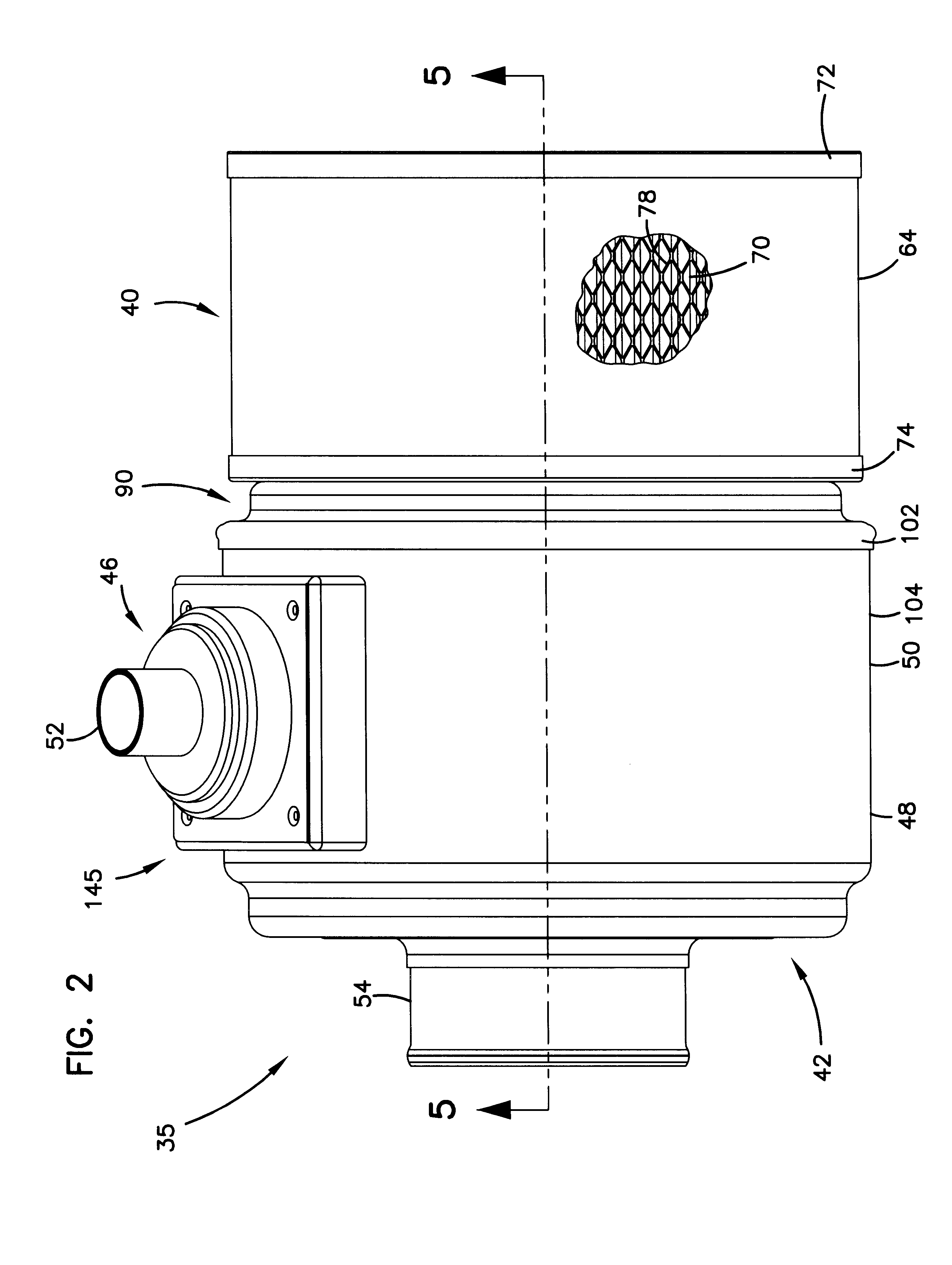
The housing 50 can be made from rolled steel, aluminum, or plastic (nylon).

The media 163 of the coalescer filter 152 can be non-pleated, non-cylindrical, fibers having an average fiber size of about 12.5 micron and a percent solidity, free state, of no greater than about 1.05%.

The housing 182 of the coalescer 152 can be a soft, compressible material, such as foamed polyurethane. The housing 182 may comprise a variety of polymeric materials moldable to form an appropriate gasket member, with media 163 potted therein. One useful material is polyurethane ...


PUM

PropertyMeasurementUnit
angleaaaaaaaaaa
particle sizeaaaaaaaaaa
sizeaaaaaaaaaa

Abstract

A filter arrangement includes a tubular first filter element having a first media pack defining a first open filter interior and an air flow outlet. The air flow outlet is in gas flow communication with the first open filter interior. A housing construction has a gas flow inlet and a gas flow outlet. The air flow outlet of the first filter element is in gas flow communication with the gas flow outlet. A coalescer filter element is oriented in the housing construction in fluid communication with the gas flow inlet. A tubular second filter element is oriented in the housing construction and has a second media pack defining a second open filter interior. The second open filter interior is in gas flow communication with the gas flow outlet.

Description

The present invention relates to systems and methods for cleaning air and separating hydrophobic fluids (such as oils), that are entrained as aerosols, from gas streams (for example, air streams). Preferred arrangements also provide for filtration of other fine contaminants, for example carbon material, from the gas streams. Methods for conducting the separations are also provided.Certain gas streams, such as blow-by gases from diesel engines, carry substantial amounts of entrained oils therein, as aerosol. The majority of the oil droplets within the aerosol are generally within the size of 0.1-10.0 microns.In addition, such gas streams also carry substantial amounts of fine contaminant, such as carbon contaminants. Such contaminants generally have an average particle size of about 0.1-1 microns.In some systems, it is desirable to vent such gases to the atmosphere. In general, it is preferred that before the gases are vented to the atmosphere, the gases be cleaned of a substantial p...

Claims


Application Information

Patent Timeline
Patent Type & Authority Patents(United States)
IPC IPC(8): B01D46/24F01M13/04F01M13/00B01D46/00B01D46/52
CPCB01D46/0024B01D46/003B01D46/2411B01D46/521F01M13/04B01D2271/022B01D46/64
Inventor GIESEKE, STEVEN SCOTTDUSHEK, ROBERT ALLEN
Owner DONALDSON CO INC
Why Eureka
Try Eureka