
Thermal fuse

a technology of thermal fuse and fuse rod, which is applied in the direction of thermally actuated switches, electric switches, electrical apparatus, etc., can solve the problems of quality problems and the possibility of soldering points shattering after a long tim

Inactive Publication Date: 2011-07-28
ROBERT BOSCH GMBH
View PDF17 Cites 14 Cited by
  • Summary
  • Abstract
  • Description
  • Claims
  • Application Information

AI Technical Summary

Benefits of technology

[0006]The object of the present invention is therefore to make available a thermal fuse of the abovementioned type which triggers more reliably.
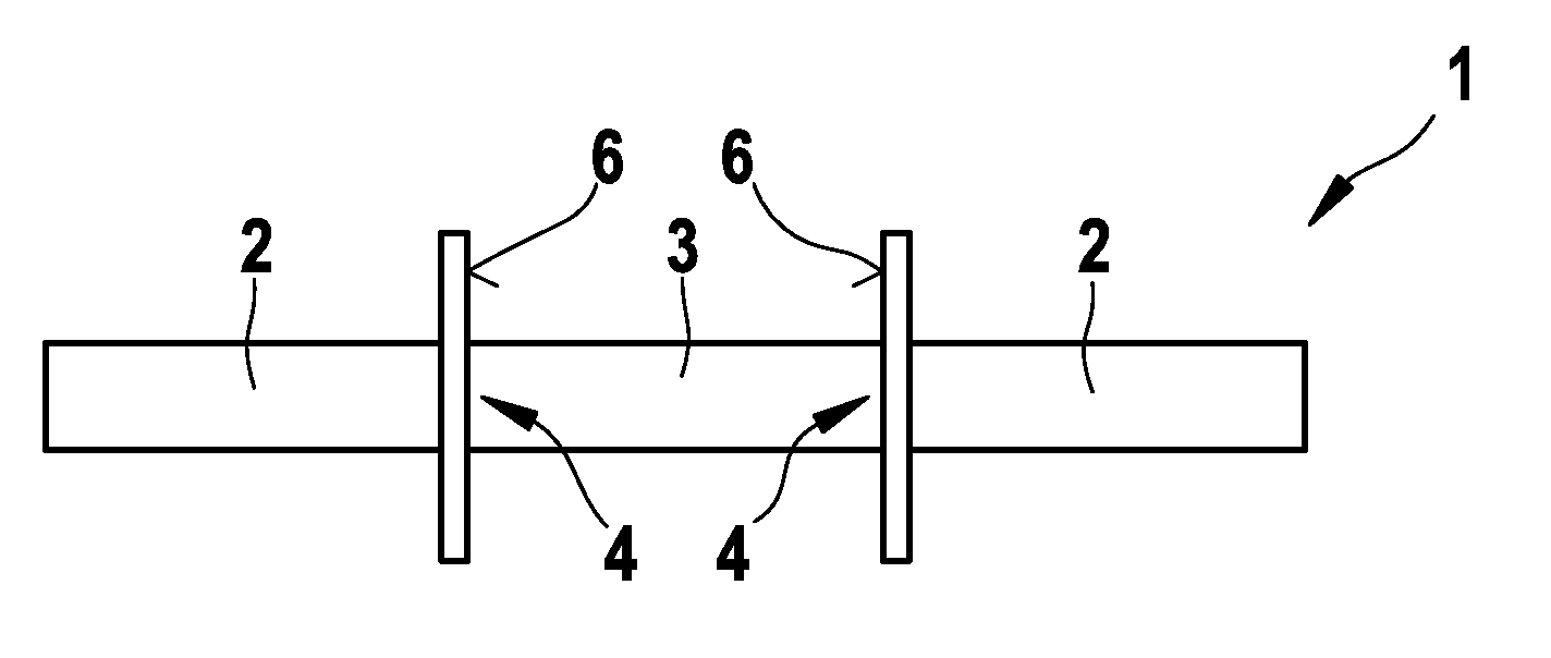
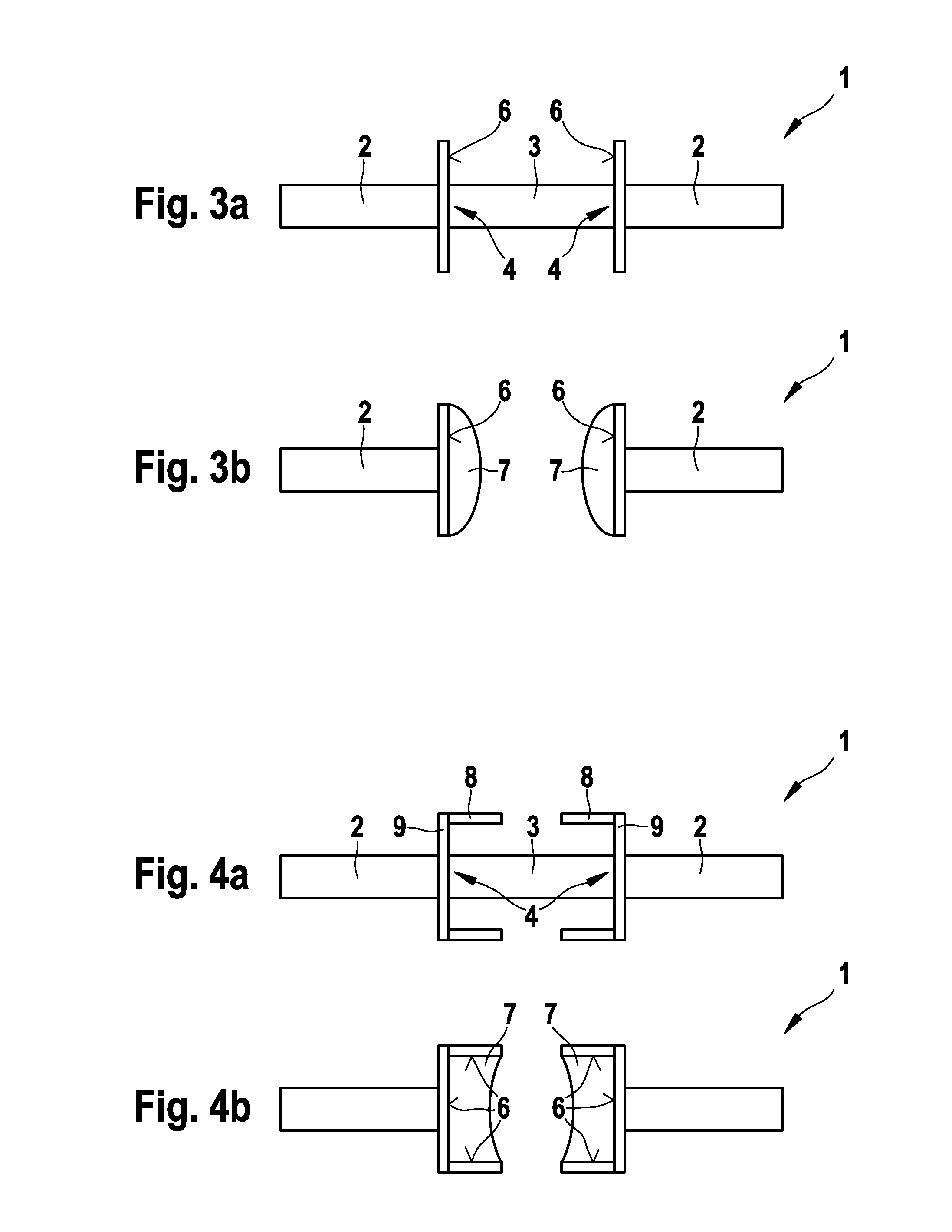
[0008]One concept of the above thermal fuse is to construct the expansion regions for accommodating the molten fusible material in such a way that, when triggering occurs, the separation of the current path by the fusible element is assisted by use of the surface tension of the molten fusible material. In particular, the connecting elements in the expansion region have a surface structure in which, in particular, an energy barrier to the expansion of the molten fusible material is avoided. This can be achieved, in particular, by virtue of the fact that the expansion surface is provided only with curvatures of 0 or with positive curvatures, and in particular negative curvatures are avoided in order to reduce the surface energy. It is therefore possible to minimize the risk of bridges composed of fusible material remaining between the connecting regions of the thermal fuse.

Problems solved by technology

In this context, even in the non-triggered case, a mechanical force is continuously applied to the connecting point, which can lead to quality problems, specifically in the case of long periods of use such as, for example, the long operating times in the automotive field.
In particular, the soldering point may shatter after some time.

Method used


Image

  • Thermal fuse
  • Thermal fuse
  • Thermal fuse

Examples


Embodiment Construction

[0021]In the following description, identical reference symbols denote elements with an identical or comparable function.

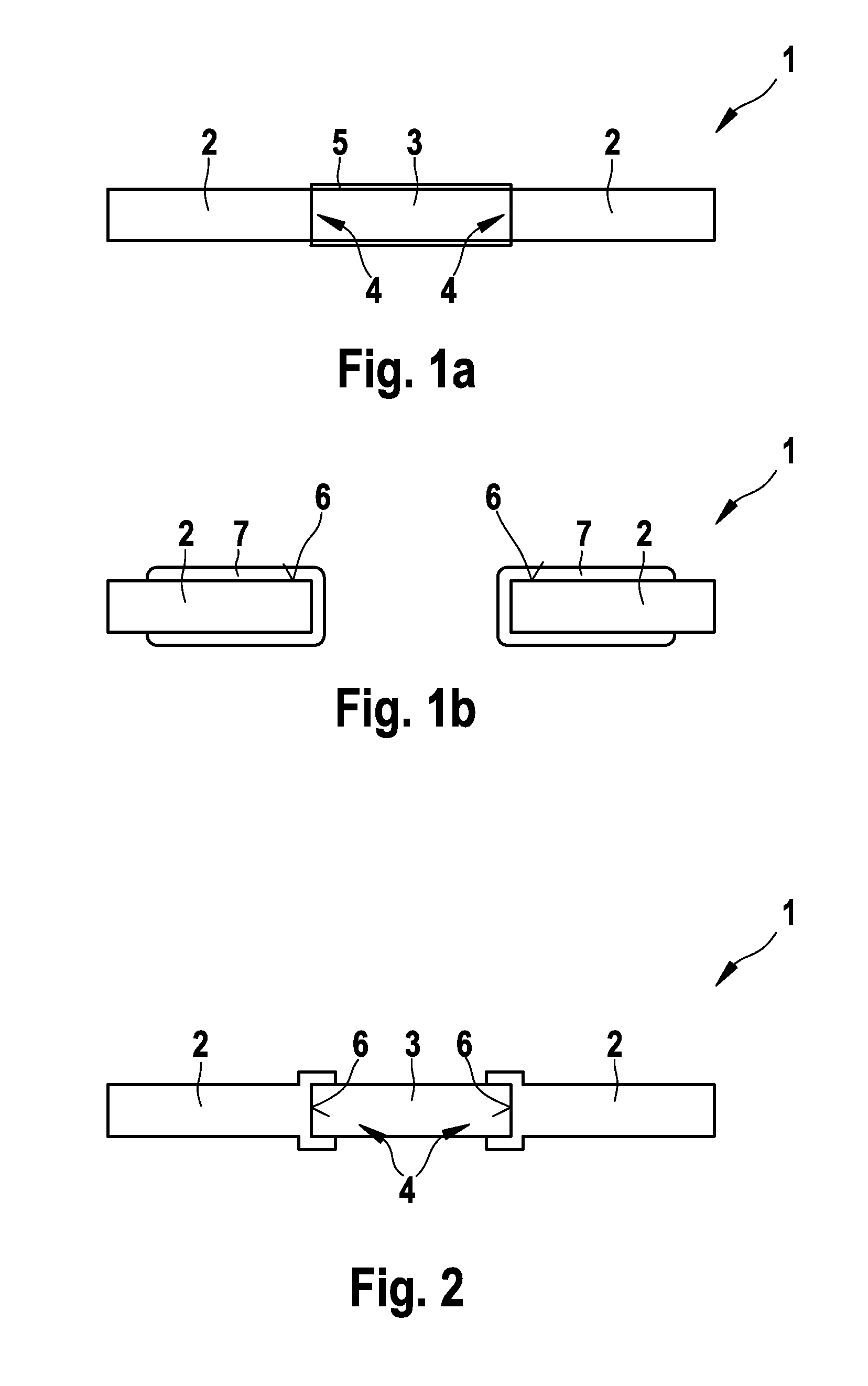
[0022]FIGS. 1a and 1b illustrate a conventional thermal fuse 1 which has two connecting elements 2 between which a conductive fusible element 3 is arranged. The fusible element 3 is fastened, for example soldered, by its two ends to a respective connecting region 4 of the connecting lines 2. The cross section of the connecting elements 2 at the contact site with the fusible element 3 and the cross section at the ends of the fusible element 3 are essentially identical, with the result that the connecting elements 2 merge, with respect to their surfaces, essentially flush with the fusible element 3.

[0023]If the ambient temperature of the thermal fuse 1 exceeds a threshold value, the fusible material of the fusible element 3 melts. The fusible material of the fusible element is preferably a metal or an alloy such as, for example solder, which has a low melting point ...


PUM


Abstract

The invention relates to a thermal fuse (1) for interrupting a power flow in modules, particularly for use in the automotive field, comprising: - a connecting element having a connecting region, - a fusible element (3) composed of fusible material and attached with one end to the connecting region (2) in order to establish an electrically conductive connection between the fusible element (3) and the connecting element (2), the connecting element (2) comprising an expansion region for accommodating melted fusible material, characterized in that the expansion region has an expansion surface (6) on which part of or all of the melted fusible material spreads as the fusible element melts, the expansion surface (6) having no positive curvature.

Description

BACKGROUND OF THE INVENTION[0001]The invention relates to a thermal fuse for interrupting a power flow in modules, in particular for use in the automotive field.[0002]In order to protect electric modules against overheating, irreversible thermal fuses are required which, at an excessively high ambient temperature, interrupt a power-conducting conductor, that is to say trigger the fuse. The thermal fuses are configured here in such a way that the triggering temperature is not reached as a result of a high power flow, so that it is ensured that said thermal fuses cannot be triggered by a high current but rather only by an excessively high ambient temperature. A thermal fuse of the abovementioned type therefore serves to make available an independent switch-off path for electric modules, wherein the power flow is reliably interrupted when there are unacceptably high temperatures in the module, for example owing to failures of components, short-circuits, for example due to an extraneous...

Claims


Application Information

Patent Timeline
Patent Type & Authority Applications(United States)
IPC IPC(8): H01H85/05
CPCH01H37/761H01H37/76H01H85/04
Inventor SCHULZE-ICKING-KONERT, GEORGSEEBACHER, DANIEL
Owner ROBERT BOSCH GMBH
Learn More