High integrity touch screen system

a touch screen system, high integrity technology, applied in the direction of error detection/correction, instruments, computing, etc., can solve the problems of occupant discomfort, high error rate, and general reliability, and achieve the effect of improving the comfort of users

Active Publication Date: 2011-07-28
HONEYWELL INT INC
View PDF4 Cites 49 Cited by
  • Summary
  • Abstract
  • Description
  • Claims
  • Application Information

AI Technical Summary

Benefits of technology

[0020]Various embodiments of a high integrity touch screen system for enabling an operator to interact with a commanded system are disclosed herein. In a first non-limiting embodiment, the touch screen system includes, but is not limited to, a display screen that is configured to present information to an operator. A first sensor array is arranged proximate the display screen and is configured to detect a touch by the operator on the display screen and to generate a first set of touch position coordinates. A first processor is communicatively connected to the first sensor array and is configured to receive the first set of touch position coordinates from the first sensor array. A second sensor array is arranged proximate the display screen, the second sensor array is configured to detect the touch by the operator on the display screen and to generate a second set of touch position coordinates. A second processor is communicatively connected to the second sensor array and is configured to receive the second set of touch position coordinates from the second sensor array. In this first embodiment, the first processor and the second processor are communicatively connected to each other and the first processor and the second processor are further configured to cooperate to compare the first set of touch position coordinates with the second set of touch position coordinates and to invalidate the touch when the first set of touch position coordinates and the second set of touch position coordinates do not substantially coincide.
[0021]In a second non-limiting embodiment, a high integrity touch screen system includes, but is not limited to, a display screen that is configured to present information to an operator. A first sensor array is arranged proximate the display screen. The first sensor array is configured to detect a touch by the operator on the display screen and to generate a first set of touch position coordinates. A first processor is communicatively connected to the first sensor array and to the display screen and is configured to receive the first set of touch position coordinat

Problems solved by technology

Each technology, while generally reliable, has an associated error rate.
Accordingly, each touch screen system employing any one of these technologies may occasionally incorrectly determine the location of the operator's touch or may detect a touch at a time when the operator did not touch the touch sensitive screen.
For other applications, however, an error could have very serious consequences.
For example, the avionics system of an aircraft in flight would require a control system that has an exceedingly low error rate because the commanded system on the aircraft may directly control the aircraft's flight performance and could therefore have a direct impact on passengers and flight crew.
A minor event has a slight reduction in safety margins; a major event has a significant reduction in safety margins and may result in some occupant discomfort; a hazardous event has a large reduction in safety margins and may have adverse effects upon occupants; a catastrophic event can result in conditions which prevent safe landing and loss of aircraft.
One aspect is simply failure to operate, but where the pilot either knows equipment is nonoperational and takes appropriate action, or the system is designed such that a failure of one element results in another part of the system compensating with or without the pilot's knowledge.
For example, a permanent failure can be the breaking of a wire or the c

Method used


Image

  • High integrity touch screen system
  • High integrity touch screen system
  • High integrity touch screen system

Examples


Embodiment Construction

[0028]The following detailed description is merely exemplary in nature and is not intended to limit the invention or the application and uses of the invention. Furthermore, there is no intention to be bound by any theory presented in the preceding background or the following detailed description.

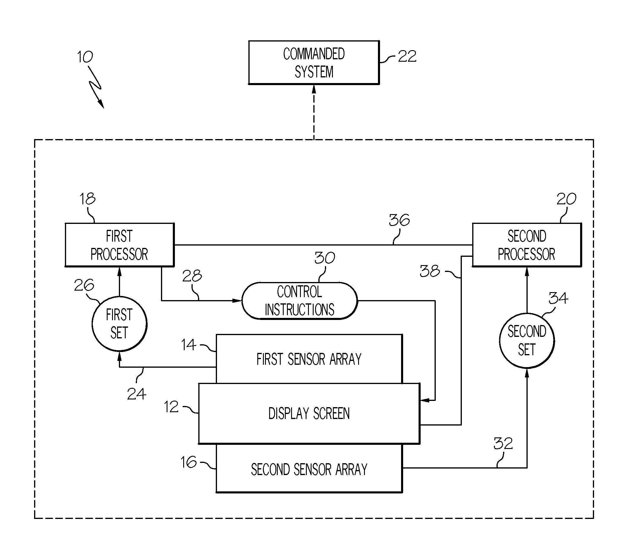
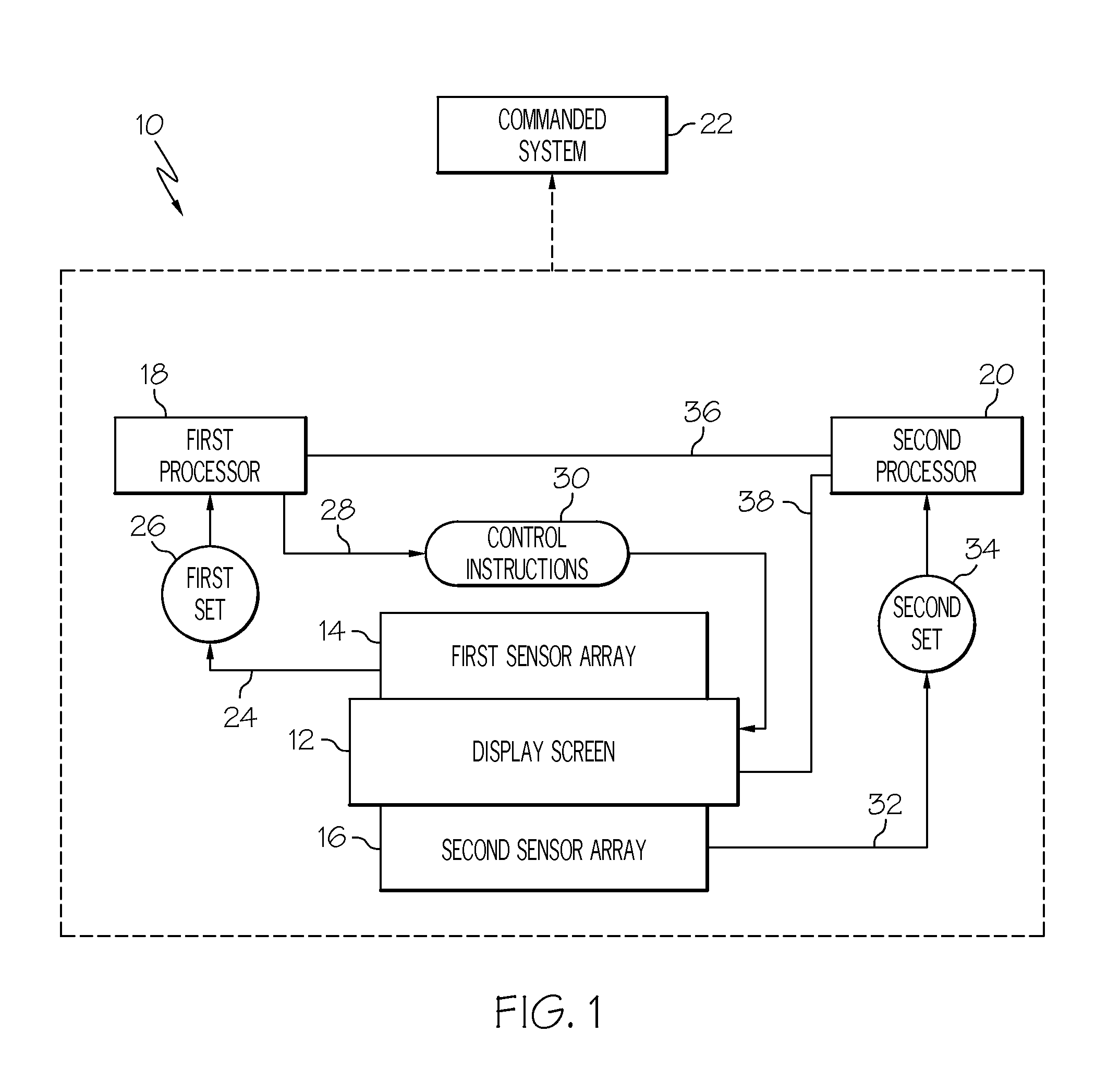
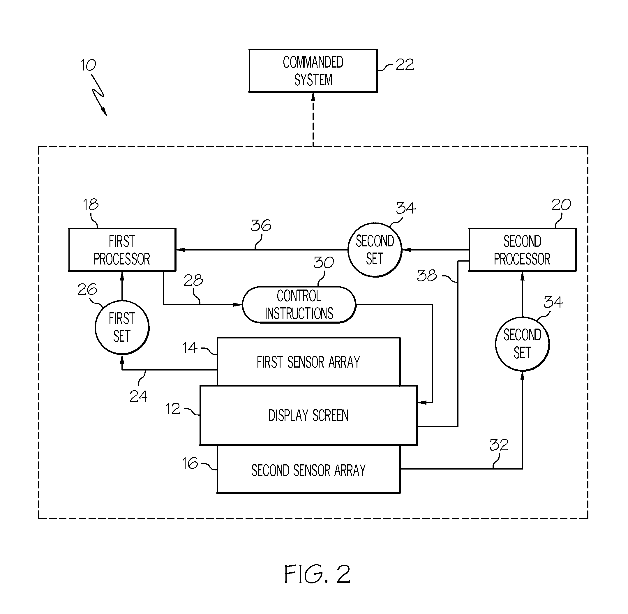
[0029]It is desired is to advance the state of the art to have a touch panel with the integrity to allow for single actions with high integrity to control a system. That is, the pilot can command the action in a single action in a manner similar to using a switch or a knob with high integrity. This requires a touch screen and touch screen supporting electronics to form a touch function with special attributes, which is the subject of this disclosure. For high integrity situations, other touch screen implementations in the past required the “arm / command” approach. Or, if multiple sensor systems were implied, previously they assumed a single processor or operation system performing comparisons...


PUM


Abstract

A high integrity touch screen system includes, but is not limited to, a display screen, a first sensor array to detect a touch on the display screen and to generate a first set of touch position coordinates, a first processor connected to the first sensor array and configured to receive the first set of touch position coordinates, a second sensor array to detect the touch on the display screen and to generate a second set of touch position coordinates and a second processor connected to the second sensor array and configured to receive the second set of touch position coordinates. The first processor and the second processor cooperate to compare the first set of touch position coordinates with the second set of touch position coordinates and to invalidate the touch when the first set of touch position coordinates and the second set of touch position coordinates do not substantially coincide.

Description

TECHNICAL FIELD[0001]The present invention generally relates to high integrity touch screen systems and more particularly, to high integrity touch screen systems which enable an operator to issue a command with only a single action.BACKGROUND[0002]Touch screen systems are control systems that are commonly used to control electrical, mechanical and computer systems (hereinafter, “commanded systems”). Touch screen systems present information to an operator with a display screen that is adapted to detect a touch (e.g., physical contact or near physical contact made using a body part, a stylus, and / or a light projector (infra red, laser, etc. . . . ). The operator provides an input into a touch screen system by touching the touch sensitive screen. For example, the operator may be presented with images on the display screen that include both text and collocated or associated graphics (e.g. a textual question and closely located “yes” and “no” boxes) and the operator may input a selection...

Claims


Application Information

Patent Timeline
IPC IPC(8): G06F3/041
CPCG06F3/0418G06F2203/04106G06F11/1637G06F11/1633
Inventor GROTHE, STEVENUTARO, JOSEPH J.TYRRELL, JAMES
Owner HONEYWELL INT INC
Why Eureka
Try Eureka