Visual inspection-based generator retention assembly tightness detection

a technology of tightness detection and visual inspection, applied in the direction of mechanical measurement arrangement, optical apparatus testing, instruments, etc., can solve the problems of catastrophic failure of electric generators, inspections, loosening of statator wedges,

Active Publication Date: 2011-07-28
GENERAL ELECTRIC CO
View PDF21 Cites 15 Cited by
  • Summary
  • Abstract
  • Description
  • Claims
  • Application Information

AI Technical Summary

Problems solved by technology

Over time, stator wedges may become loose.
If a stator wedge becomes loose, it can permit a stator coil to vibrate, which can cause catastrophic failure in an electric generator.
Such inspections present a challenge, because ripple springs are difficult to access within a generator and are concealed by the stator wedge.
There are significant challenges associated with the conventional approaches to testing ripple-spring tightness.
The second approach, using a depth gauge to take measurements through pre-formed test holes, is time consuming and is only possible in generators having stator wedges with pre-formed test holes.

Method used


Image

  • Visual inspection-based generator retention assembly tightness detection
  • Visual inspection-based generator retention assembly tightness detection
  • Visual inspection-based generator retention assembly tightness detection

Examples


Embodiment Construction

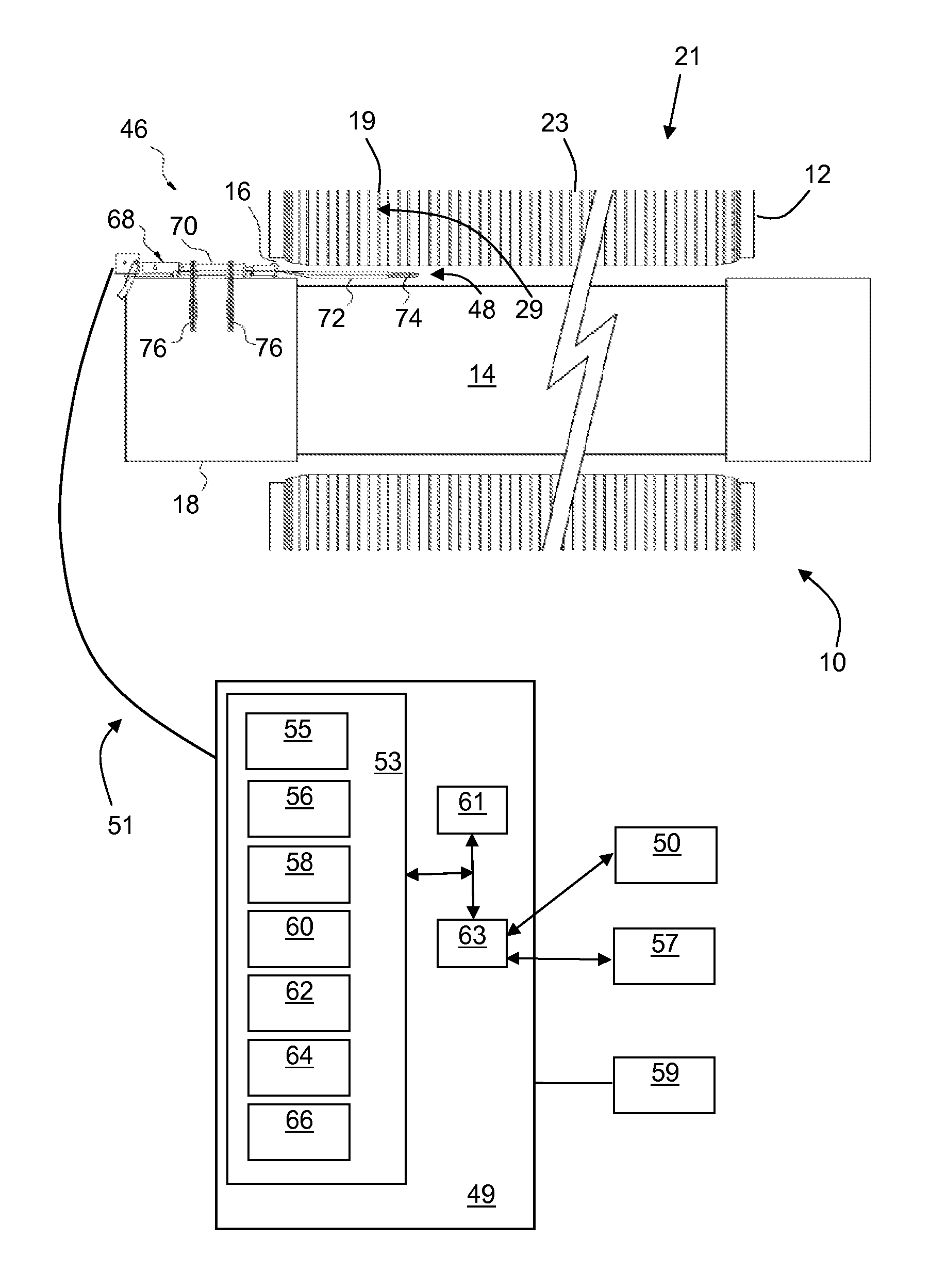
[0018]At least one embodiment of the present invention is described below in reference to its application in connection with the operation of a dynamoelectric machine. Although embodiments of the invention are illustrated relative to a dynamoelectric machine in the form of a generator, it is understood that the teachings are equally applicable to other electric machines including, but not limited to motors. Further, at least one embodiment of the present invention is described below in reference to a nominal size and including a set of nominal dimensions. However, it should be apparent to those skilled in the art that embodiments of the present invention are likewise applicable to any suitable generator and / or engine. Further, it should be apparent to those skilled in the art that embodiments of the present invention are likewise applicable to various scales of the nominal size and / or nominal dimensions.

[0019]As indicated above, aspects of the invention provide an apparatus and meth...


PUM


Abstract

A method and apparatus for visually detecting and measuring retention assembly tightness are disclosed. In an embodiment, an optical device is used to obtain at least an image of a retention assembly, the optical device being insertable into a slot between two stator core laminations and directable toward a side view of the retention assembly. The image is displayed on a display, and a measurer is used to determine a tightness of a retention assembly.

Description

BACKGROUND OF THE INVENTION[0001]The invention relates generally to the assessment of the condition of dynamoelectric machines. More particularly, the invention relates to a visual inspection-based method and apparatus for measuring the tightness of retaining ripple springs in dynamoelectric machines, particularly electric generators.[0002]Dynamoelectric machines such as electric generators include a rotor and a stator. Rotors are generally constructed from a steel forging and include a number of slots that run the length of the rotor. Rotors are electrically wound by placing conductors referred to as rotor windings into the slots of the rotor.[0003]Stators are generally constructed from a number of stacked, metal laminations. Stators also include slots, which run the length of the stator. Stators are electrically wound by placing conductors known as stator coils into the armature slots of the stator.[0004]Conventional stator coils are frequently held in place in stator slots using ...

Claims


Application Information

Patent Timeline
Patent Type & Authority Applications(United States)
IPC IPC(8): G01B11/14G06F19/00
CPCG01B11/14H02K15/0018G01M11/081G01B11/02G01B11/022G01M11/00G01N21/8806G01R31/343G01R31/50
Inventor REED, FRANCIS ALEXANDERRONEY, JR., ROBERT MARTIN
Owner GENERAL ELECTRIC CO
Why Eureka
Try Eureka