Eureka AIR delivers breakthrough ideas for toughest innovation challenges, trusted by R&D personnel around the world.

Apparatus and method for sequential bagging of materials

a bag and bag mouth technology, applied in the field of bagging materials, can solve the problems of preventing proper expansion of the bag in use, affecting the quality of the bag, and inability to hold the bag mouth, so as to prevent premature separation from the pack and allow full distension of the bag mouth during loading

Inactive Publication Date: 2011-08-04
BRESLEND PATRICK RYAN
View PDF4 Cites 0 Cited by
  • Summary
  • Abstract
  • Description
  • Claims
  • Application Information

AI Technical Summary

Benefits of technology

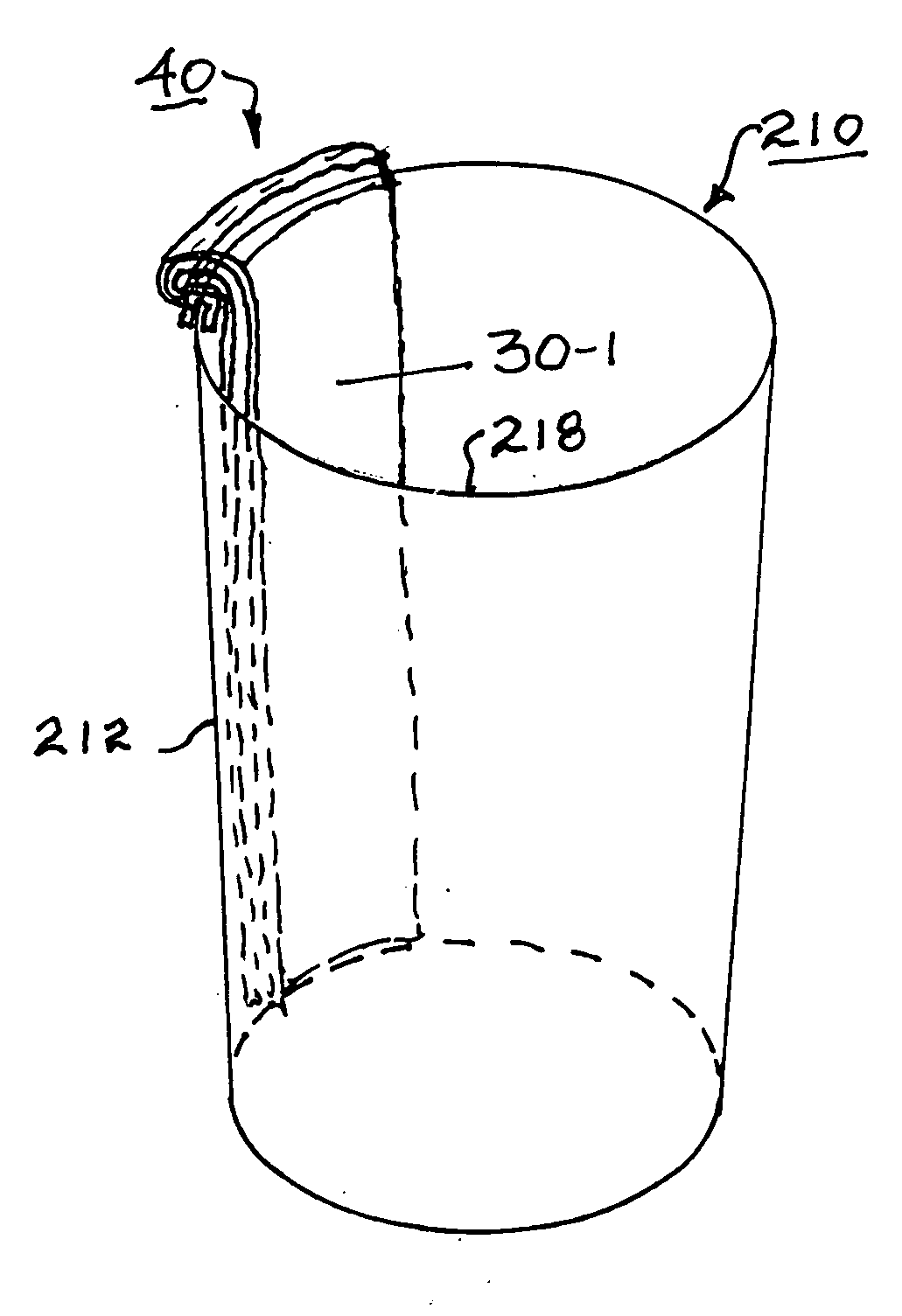
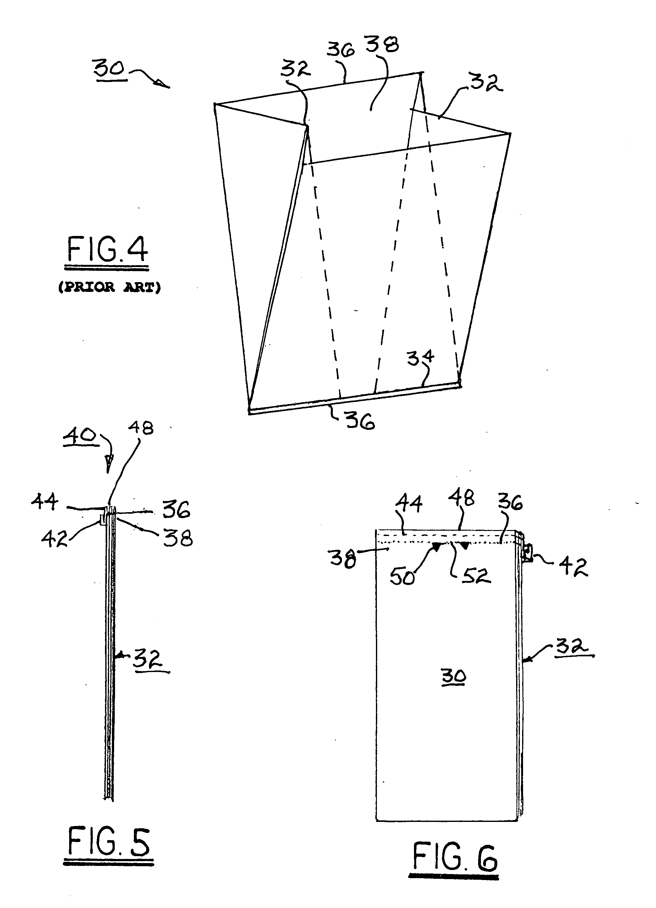
[0012]The bag portions of the bag pack are contained within the structure which has a plurality of lips in the case of a rectangular structure, or a single circular lip in the case of a cylindrical structure. The bag-attachment portion is folded outwards over a lip to capture and secure the bag pack in the structure. This arrangement also captures the rear edge of the bag currently in use outside of and below the lip, thereby preventing premature separation from the pack and permitting full distension of the bag mouth during loading. The front edge of the outermost bag of the pack is separated from the bag-attachment portion and is drawn over another lip, preferably an opposing lip, or over the remainer of the circular lip in the case of a cylindrical structure, to open the bag for loading. The rear edge remains attached to the bag pack, thus fully distending the mouth of the bag.

Problems solved by technology

A shortcoming of a structure closed on the sides is that the new bag can undesirably trap air between the bag and the wall of the structure, thus inhibiting proper expansion of the bag in use.
Obtaining each bag from a remote source as needed and installing the bag into the receptacle is time-consuming for a worker and thus is cost-inefficient.
Further, such applications wherein each full bag must be lifted out of the structure are physically demanding of workers and can give rise to back injuries in the work force.
However, each dispensed bag is supported only loosely on the left and right edges by frame rails extending through openings along the edges of the bag mouth, and thus the mouth of the bag is not held fully open by the device, making it somewhat difficult for a worker to load successive items into the bag.
Further, the bag is not prevented by the frame from being separated prematurely and undesirably from the pack.

Method used


Image

  • Apparatus and method for sequential bagging of materials
  • Apparatus and method for sequential bagging of materials
  • Apparatus and method for sequential bagging of materials

Examples


Embodiment Construction

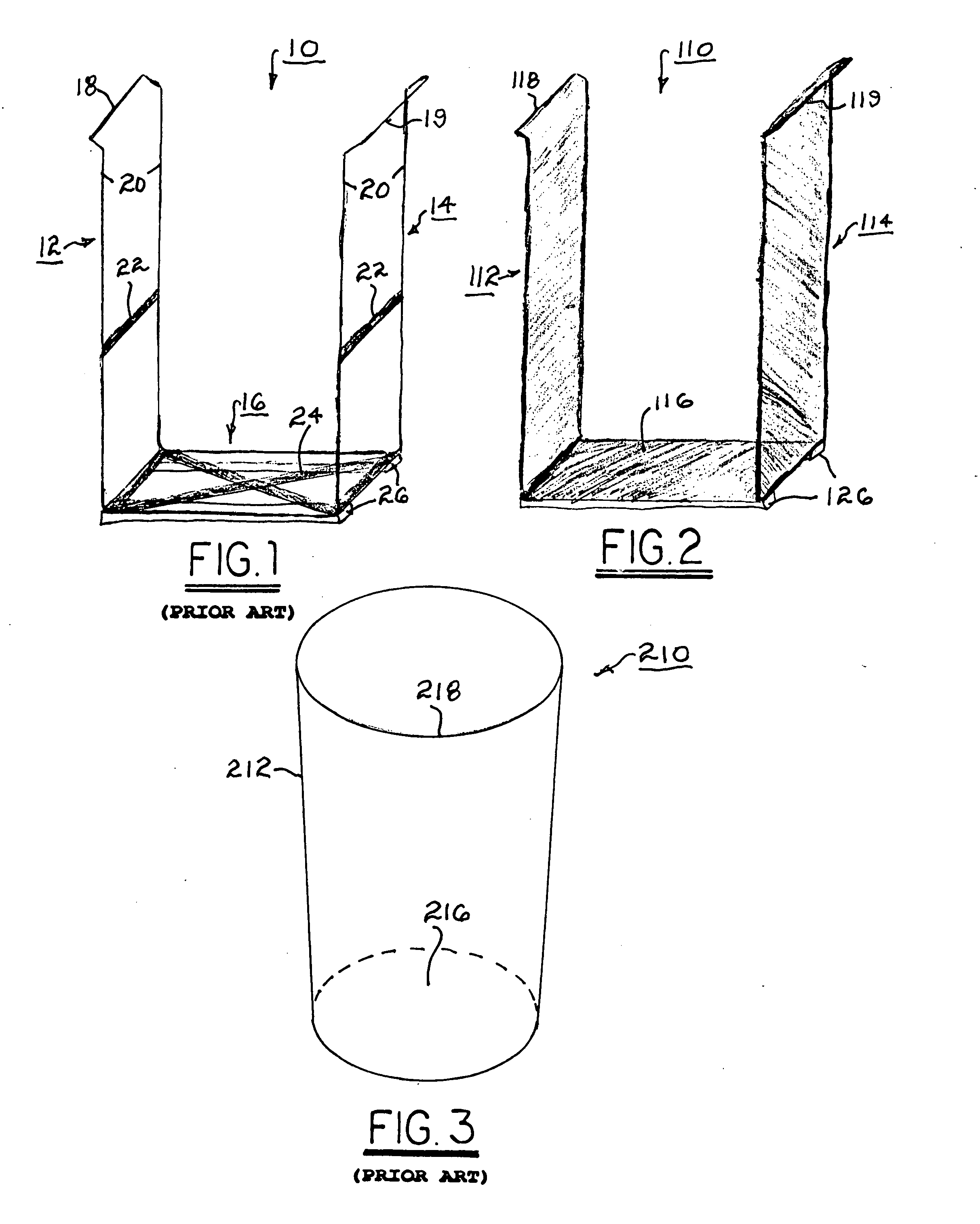
[0028]Referring to FIGS. 1 through 3, structures 10,110,210 are shown that may be incorporated into a system in accordance with the present invention, as described hereinbelow.

[0029]Referring to FIG. 1, prior art structure 10 is a framework formed typically of bent and welded metal rod, comprising first and second open upright sides 12,14 connected by a bottom 16, and terminating at first and second lips 18,19 which preferably but not necessarily are flared outward. The upright elements 20 of sides 12,14 may be connected by one or more horizontal straps 22, and bottom 16 may be reinforced by X-shaped or other reinforcing 24. Bottom 16 may be supported by one or more skids 26 and / or casters (not shown) to facilitate moving structure 10. Typically, virtual third and fourth sides extending between sides 12,14 are omitted to permit removal of a bag of materials from structure 10 laterally through either virtual side, although either or both of those sides may be provided as may be desir...


PUM

PropertyMeasurementUnit
shapeaaaaaaaaaa
structureaaaaaaaaaa
flexibleaaaaaaaaaa

Abstract

A system comprising a multiple-bag pack supported for dispensing, loading, and removal of bags on a structure. The pack includes a bag-attachment portion wherein the multiple bags are sequentially attached. Each bag is removable in sequence by separation from the pack along a parting feature. The bags are contained within the structure and the bag-attachment portion is folded outwards over a lip to secure the bag pack. The front edge of the outermost bag of the pack is drawn over another lip to open the bag for loading. The rear edge remains attached to the bag pack, thus fully distending the mouth of the bag. To change bags, the rear edge of the bag is separated from the pack and the first lip along the parting structure. The front edge of the loaded bag is removed from the second lip, and the bag is closed and removed from the structure.

Description

TECHNICAL FIELD[0001]The present invention relates to the practice of bagging materials for subsequent transport; more particularly, to bagging practice wherein a plurality of bags are used sequentially over time; and most particularly, to a system (apparatus and method) for sequential bagging of materials wherein a plurality of bags to be used are stored in and dispensed from a bag-loading device comprising a frame structure that both supports each bag over opposing edges of the structure and distends the mouth of each bag for loading.BACKGROUND OF THE INVENTION[0002]It is well known to accumulate and transport materials in single-use flexible bags. This practice is used in activities ranging at least from residential and restaurant waste disposal, to industrial collection and shipping of in-transit letters and packages by delivery companies, to bagging of purchased items in department stores and supermarkets.[0003]In some prior art applications, such as in bagging fruits and veget...

Claims


Application Information

Patent Timeline
Patent Type & Authority Applications(United States)
IPC IPC(8): B65B1/04B65B7/00
CPCB65B7/00B65B1/04B65D33/001B65B67/12
Inventor BRESLEND, PATRICK RYAN
Owner BRESLEND PATRICK RYAN
Why Eureka
Eureka Blog
Learn More