
Horseshoe load cell

a load cell and horseshoe technology, applied in the field of load cells, can solve the problems of slow and awkward, rod rotators may further complicate the installation process, and the installation and removal process can be even more complicated, so as to maximize measurement accuracy, efficient and effective deformation analysis, and effective measurement method

Inactive Publication Date: 2011-08-04
MACKIE DAN
View PDF23 Cites 9 Cited by
  • Summary
  • Abstract
  • Description
  • Claims
  • Application Information

AI Technical Summary

Benefits of technology

[0010]In view of the foregoing disadvantages inherent in the known load cells art, the present invention provides a novel horseshoe load cell system. The general purpose of the present invention, which will be described subsequently in greater detail is to provide efficient and effective deformation analysis to track polished rod loading in oilfield oil pump installations.
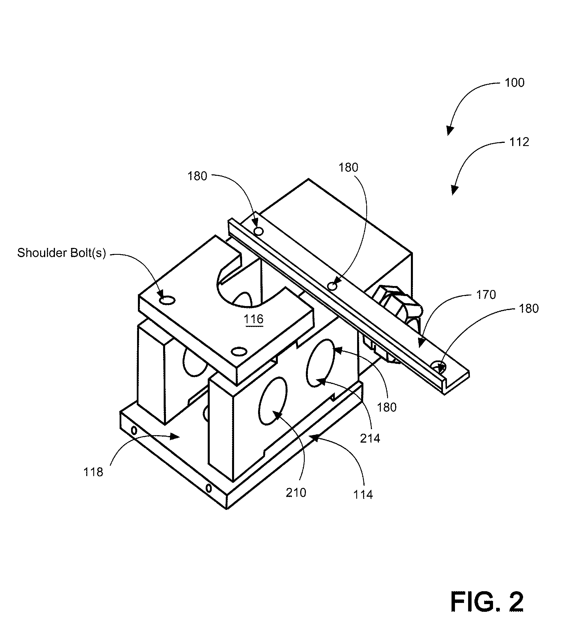
[0011]A horseshoe load cell system adapted to be removably attached to a polished rod on an oilfield pump jack is disclosed herein comprising: at least one horseshoe load cell acting as a transducer for converting a measured force acting on the polished rod into an electrical signal via a plurality of strain gauges. The device further comprises an electric circuit connected to the plurality of strain gauges (preferably 8) to establish the electrical signal in relation to the sensed force. Top washers and bottom washers are used to hold the horseshoe load cell in a proper position on the polished rod. Retaining shoulder bolts are also included for removably retaining the horseshoe load cell to the polished rod via the bridle plates. The device additionally has a top bridle plate; a bottom bridle plate; at least one retaining plate; an anti-rotation bar with at least one aperture for a quick link to absorb tension in a load cell cabling, and to eliminate conflicts between the load cell cabling and rod-rotator operation, reserving the cable strain relief solely for weatherproofing. The top and bottom bridle plates are spaced a distance apart via arms. The horseshoe load cell is removably received by the polished rod and secured thereon by the top and bottom bridle plates and retaining plate(s). The combination of the washers, the specially designed arms and the hole placement in the arms centers the load between the strain gauges, maximizing measurement accuracy. Eight gauges may be placed on each arm symmetrically around the rod string, providing an effective measurement method. Varying arm sizes and hole placements can be included to allow different load ratings.
[0012]A method for installing a horseshoe load cell system for measuring the load on a polished rod connected between an oilfield pump jack and a downhole pump in a subterranean producing formation is also disclosed herein comprising the steps of: standing the well off, installing the horseshoe load cell by slipping the horseshoe load cell into place placement on the polished rod, inserting top washer shoulder bolt; and reversing the standing off process. The horseshoe load cell system provides convenient, reliable and cost-effective service for oil producing entities.

Problems solved by technology

Installations of industry standard doughnut-style load cells have been conventionally used however they are known to be slow and awkward.
The existence of a rod rotator may further complicate installations, since the load cell must be placed below the rod rotator.
For large pump jacks in particular, the installation and removal process can be even more complicated, requiring the use of extra equipment, such as a bucket truck.
This can introduce additional costs and scheduling delays, making the process both time-consuming and expensive.
Further, traditional load cells may be expensive, heavy and cumbersome to work with and thus are not a cost-effective solution for oil companies to use.

Method used


Image

  • Horseshoe load cell
  • Horseshoe load cell
  • Horseshoe load cell

Examples


Embodiment Construction

[0021]As discussed above, embodiments of the present invention relate to a load cell device and more particularly to a horseshoe load cell as used to improve the optimization of sucker rod oil production. The horseshoe load cell is designed as a specific improvement over doughnut-style polished rod load cells, allowing for easy and efficient installation and removal, as well as cost-efficient repair for in-field service, thereby decreasing down-time expense. The device can be used to replace an existing polished rod load cell, and is lighter than a conventional load cell.

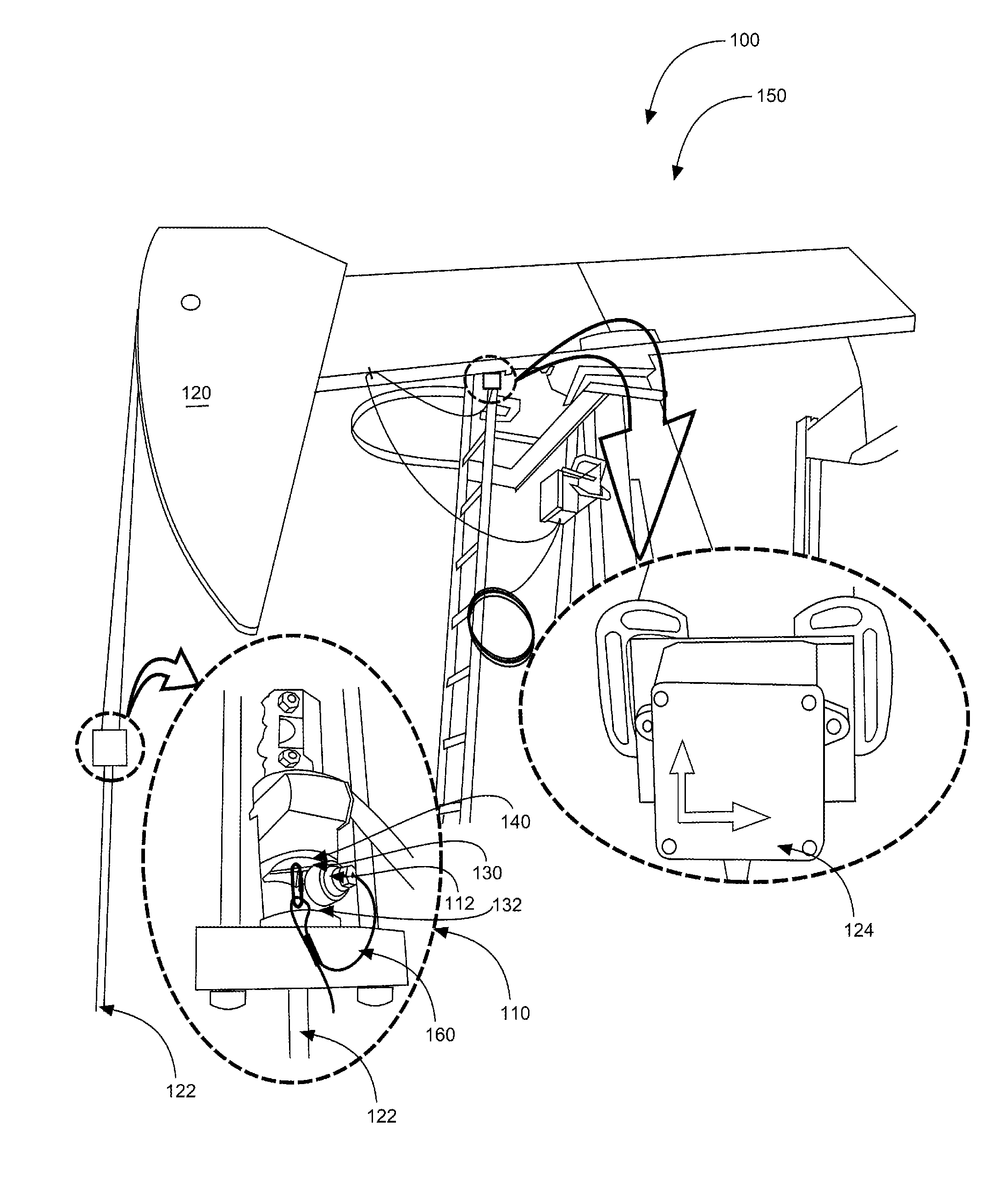
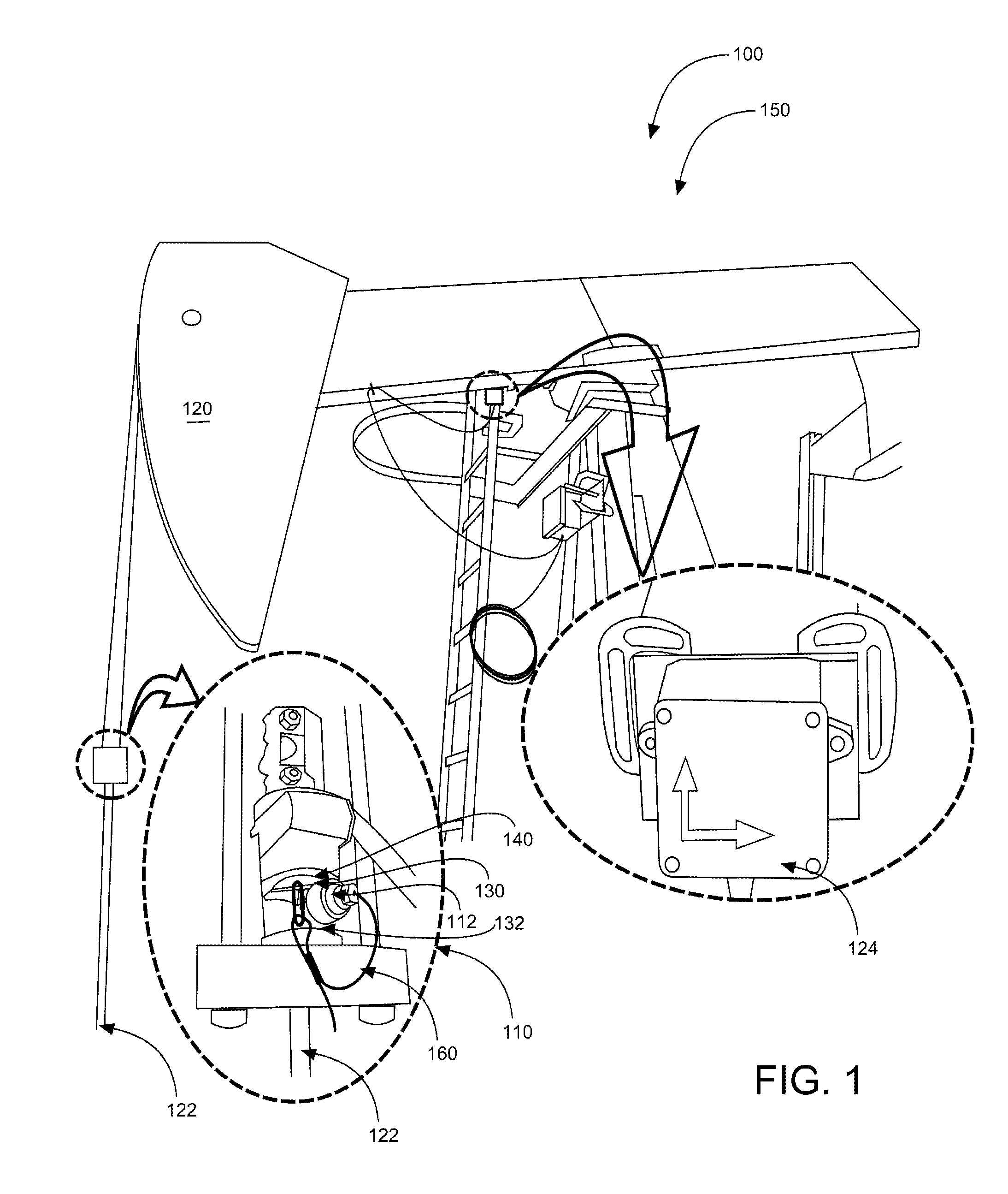
[0022]Referring to the drawings by numerals of reference there is shown in FIG. 1 a perspective view illustrating a doughnut load cell system (as replaceable by horseshoe load cell system 100 as demonstrated in FIG. 4) in an in-use condition 150 as installed on oilfield pump jack 120 according to an embodiment of the present invention. This doughnut style load cell is to be replaced with horseshoe load cell 110 as d...


PUM

PropertyMeasurementUnit
deformation forceaaaaaaaaaa
tensionaaaaaaaaaa
forceaaaaaaaaaa

Abstract

A horseshoe load cell is designed to aid in optimizing sucker rod oil production, to improve the installation and removal process for polished rod load cells. This device includes top and bottom washers, a retaining plate and associated bolts. The washers may be used to hold the load cell in the proper position on the polished rod. These washers may also be made in a variety of sizes to accommodate a range of polished rod sizes. An anti-rotation bar can be included to eliminate conflicts between load cell cabling and rod-rotator operation. The anti-rotation bar may have a hole for a quick link to absorb cable tension, reserving the cable strain relief for weatherproofing. The combination of the washers, the specially designed arms and the hole placement in the arms centers the load between the strain gauges, maximizing measurement accuracy. Two sets of strain gauges may be placed on each arm symmetrically around the rod string, providing an effective measurement method. Varying arm sizes and hole placements can be included to allow for different load ratings.

Description

CROSS-REFERENCE TO RELATED APPLICATION[0001]The present application is related to and claims priority from prior provisional application Ser. No. 61 / 299,772, filed Jan. 29, 2010 which application is incorporated herein by reference.COPYRIGHT NOTICE[0002]A portion of the disclosure of this patent document contains material which is subject to copyright protection. The copyright owner has no objection to the facsimile reproduction by anyone of the patent document or the patent disclosure, as it appears in the Patent and Trademark Office patent file or records, but otherwise reserves all copyright rights whatsoever. 37 CFR 1.71(d).BACKGROUND OF THE INVENTION[0003]1. Field of the Invention[0004]The present invention relates generally to the field of load cells and more specifically relates to horseshoe load cells.[0005]2. Description of the Related Art[0006]Pump jacks are used to pump oil to the surface by a rod which extends from the surface to a downhole pump located in a subterranean...

Claims


Application Information

Patent Timeline
Patent Type & Authority Applications(United States)
IPC IPC(8): G01L1/04E21B47/00
CPCG01L1/04E21B47/00E21B47/009E21B43/127G01L5/0061F04B47/02G01L1/2287
Inventor MACKIE, DAN
Owner MACKIE DAN
Learn More