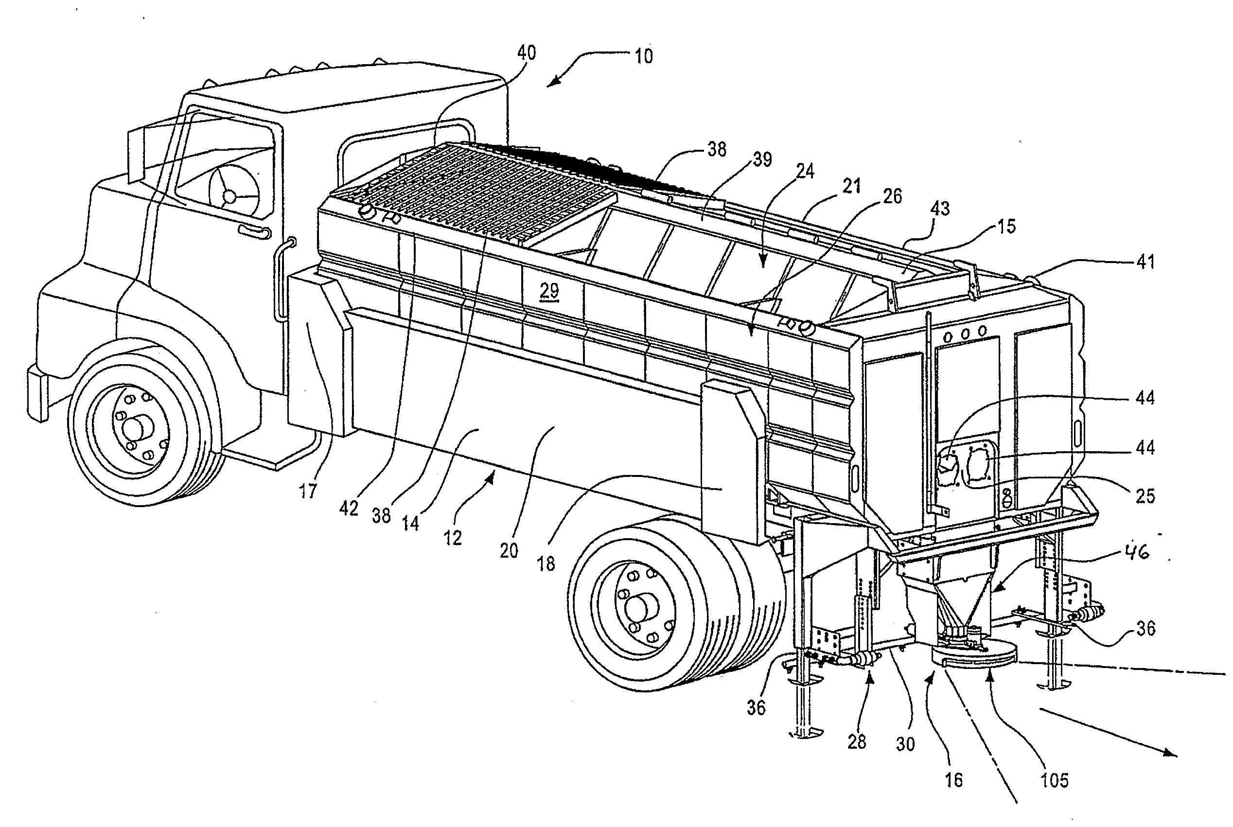
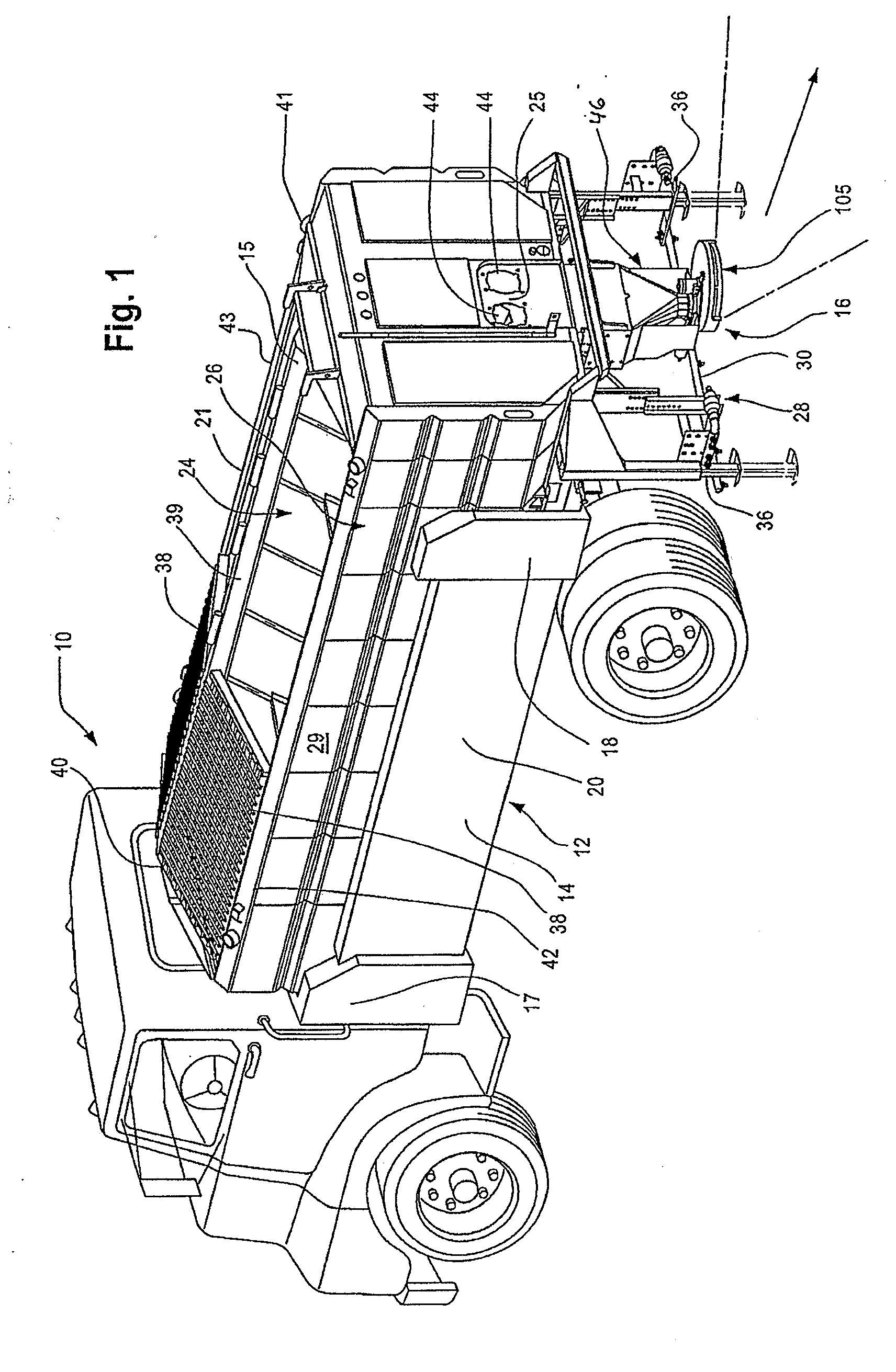
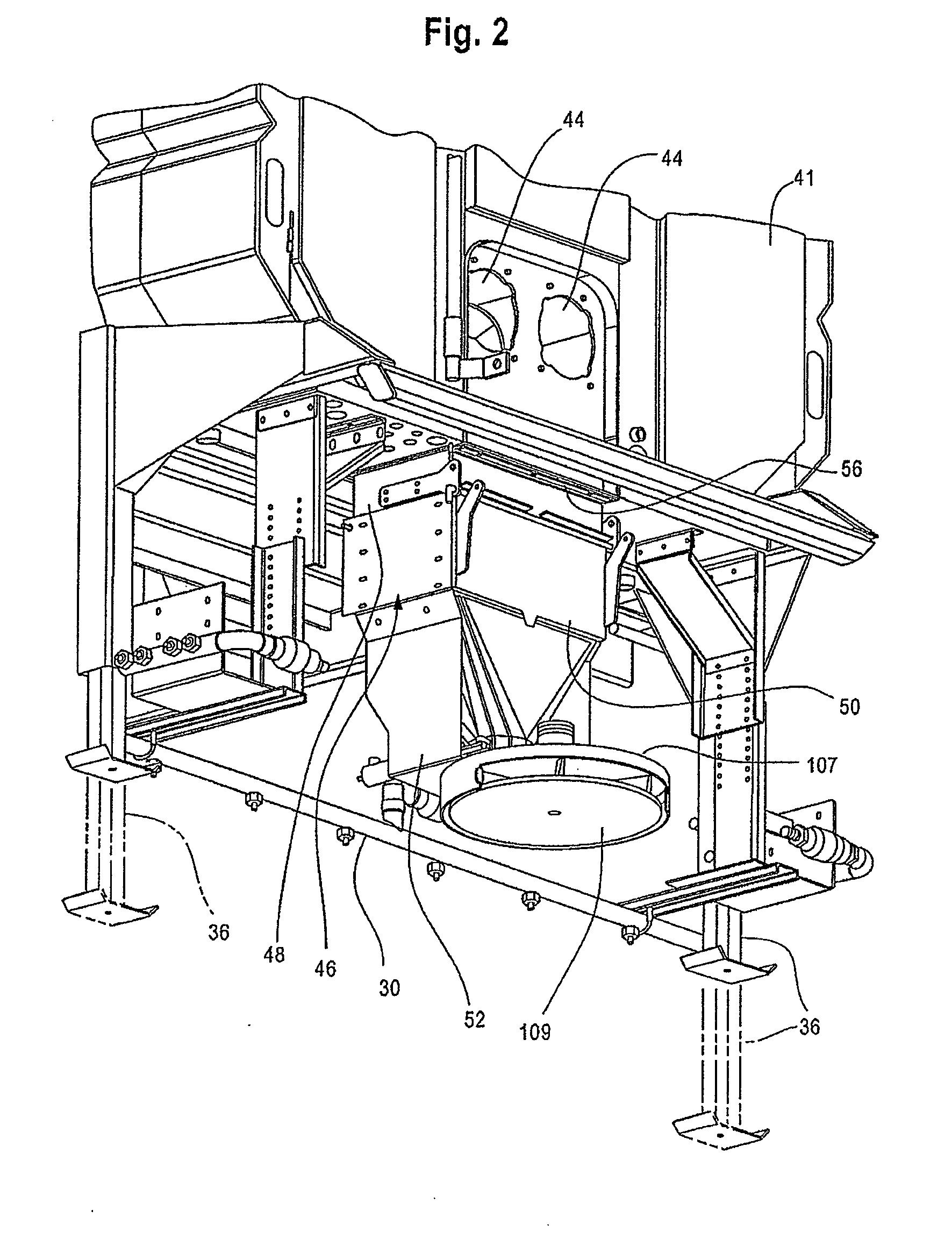
Apparatus for spreading granular materials from vehicle

a technology of granular materials and spreaders, which is applied in the direction of centrifugal wheel fertilisers, roads, ways, etc., can solve the problems of limited control over material placement, material placement itself, equipment and labor costs involved, and significant direct costs in the process

Active Publication Date: 2011-08-04
HENDERSON PRODS
View PDF27 Cites 20 Cited by
  • Summary
  • Abstract
  • Description
  • Claims
  • Application Information

AI Technical Summary

Problems solved by technology

Significant direct costs are incurred in this process, including the costs for the materials themselves as well as equipment and labor costs involved in the application of the materials.
However, such baffles and diverters provide only limited control over material placement.
However, both of these methods involve dropping material straight down onto the roadway (i.e. with no pattern control of the particles).
Both of these methods can result in efficiency problems.
Accordingly, materi...

Method used


Image

  • Apparatus for spreading granular materials from vehicle
  • Apparatus for spreading granular materials from vehicle
  • Apparatus for spreading granular materials from vehicle

Examples


example 1

In-Line Discharge Over Narrow Roadway

[0062]To apply salt or other granular material over a relatively narrow roadway directly behind a vehicle, the discharge disc assembly 105 may be set in an intermediate neutral position such that its centerline indicated by an arrow on the exterior surface of the shroud 107 is substantially in line with the centerline of the vehicle 10 (see FIG. 9b). The diverter 117 may be partially extended to cover a portion of the discharge opening 115 such that the discharge opening is narrowed to some degree.

example 2

Adjacent Lane Discharge Over Narrow Roadway

[0063]To apply salt or other granular material over a relatively narrow roadway surface adjacent to the travel path of the vehicle, the discharge disc assembly 105 may be set in an appropriate articulated position such that its discharge centerline, indicated by the arrow on the surface of the shroud 107, is disposed in the desired angle (see FIGS. 9a and 9c). The diverter 117 may be partially extended to cover a portion of the discharge opening 115 such that the discharge opening is narrowed to some degree. The procedure as described in relation to Example 1 may then be carried out.

example 3

Discharge Over Wide Surface

[0064]In the event that a broad dispensing pattern is desired, the diverter 117 may be fully retracted such that the discharge opening 115 has the maximum opening possible. With the diverter 117 in this condition, the speed of the spinner disc may be set at the maximum rate so as to produce a wide broadcast cone. The actuating cylinder 135 may be set to cycle the piston arm back and forth so as to cause a corresponding articulation of the discharge disc assembly 105 through a wide pattern during use. This procedure can provide a wide and highly dispersed broadcast pattern.

[0065]As will be appreciated, the present invention provides the material spreading system which is highly functional and which can be tuned by the operator to deliver a variety of broadcast patterns with both directional and speed control. In particular, each of the adjustments can be made independently or in conjunction with one another to provide a desired broadcast character.


PUM


Abstract

A material spreader is adapted to dispense granular material from a vehicle. The material spreader includes a feed chute having a discharge opening and a discharge disc assembly disposed below the feed chute. The discharge disc assembly includes a spinner disc adapted to receive granular material from the feed chute, a shroud disposed in at least partial covering relation to the spinner disc, and a rotational drive operatively connected to the spinner disc such that the spinner disc is rotatable within the shroud about a rotational axis. The shroud includes a pass-through opening disposed in substantially aligned relation with the discharge opening of the feed chute at a position radially removed from the central rotational axis. The discharge disc assembly is rotatably mounted in pivoting relation about a pivot axis extending through the pass-through opening and the discharge opening of the feed chute.

Description

CROSS-REFERENCE TO RELATED APPLICATIONS[0001]This patent application claims the benefit of priority to U.S. Provisional Patent Application No. 61 / 299,501, filed on Jan. 29, 2010, and entitled “Apparatus For Spreading Granular Materials From a Vehicle,” which is incorporated in its entirety herein by this reference.TECHNICAL FIELD[0002]The present invention relates generally to a vehicle with a spreader apparatus that provides for selective spreading of granular material such as sand, salt and the like, onto surfaces such as roadways. More particularly, the present invention relates to a spreader apparatus adapted to control the direction and character of the disbursement pattern to reduce waste of the granular material.BACKGROUND[0003]Many systems are available to provide for the spreading of material, such as sand, salt, gravel, asphalt and the like, onto a surface. By way of example only, a conventional dump or V-box vehicle can include a conveyor system that transports material r...

Claims


Application Information

Patent Timeline
IPC IPC(8): B05B9/03
CPCE01H10/007B05B9/03E01C19/203A01C17/001
Inventor RICHARDSON, SHANNON B.HOLLINRAKE, MARK S.WARD, MART E.UNGERER, GLENN L.
Owner HENDERSON PRODS
Why Eureka
Try Eureka