Lamp with cable connector assemblies

Inactive Publication Date: 2011-08-04
LIN BENNY
View PDF5 Cites 3 Cited by
  • Summary
  • Abstract
  • Description
  • Claims
  • Application Information

AI Technical Summary

Benefits of technology

[0008]The main objective of the invention is to provide a lamp that has an LED module and cable

Problems solved by technology

However, when the LED module is replaced, the cables securely mounted on the LED module are also replaced even though they are still durable and workable, which is uneconomical and increases the cost of the LED lamp.
However, the

Method used


Image

  • Lamp with cable connector assemblies
  • Lamp with cable connector assemblies
  • Lamp with cable connector assemblies

Examples


Example

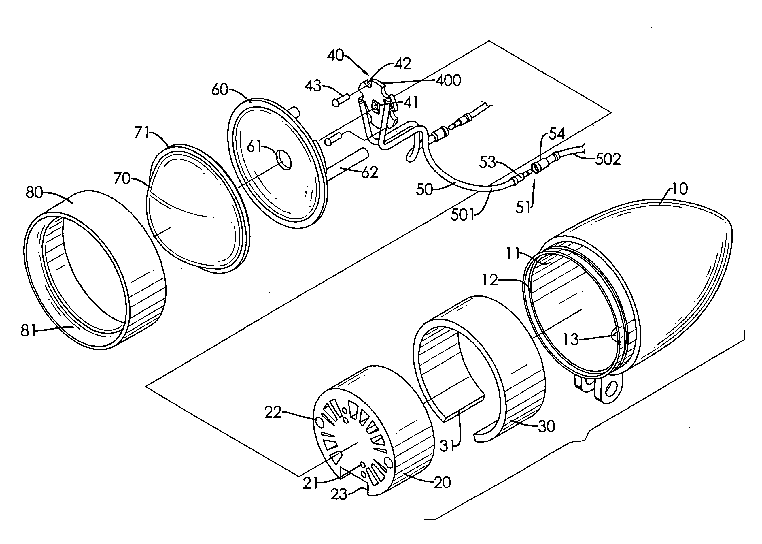
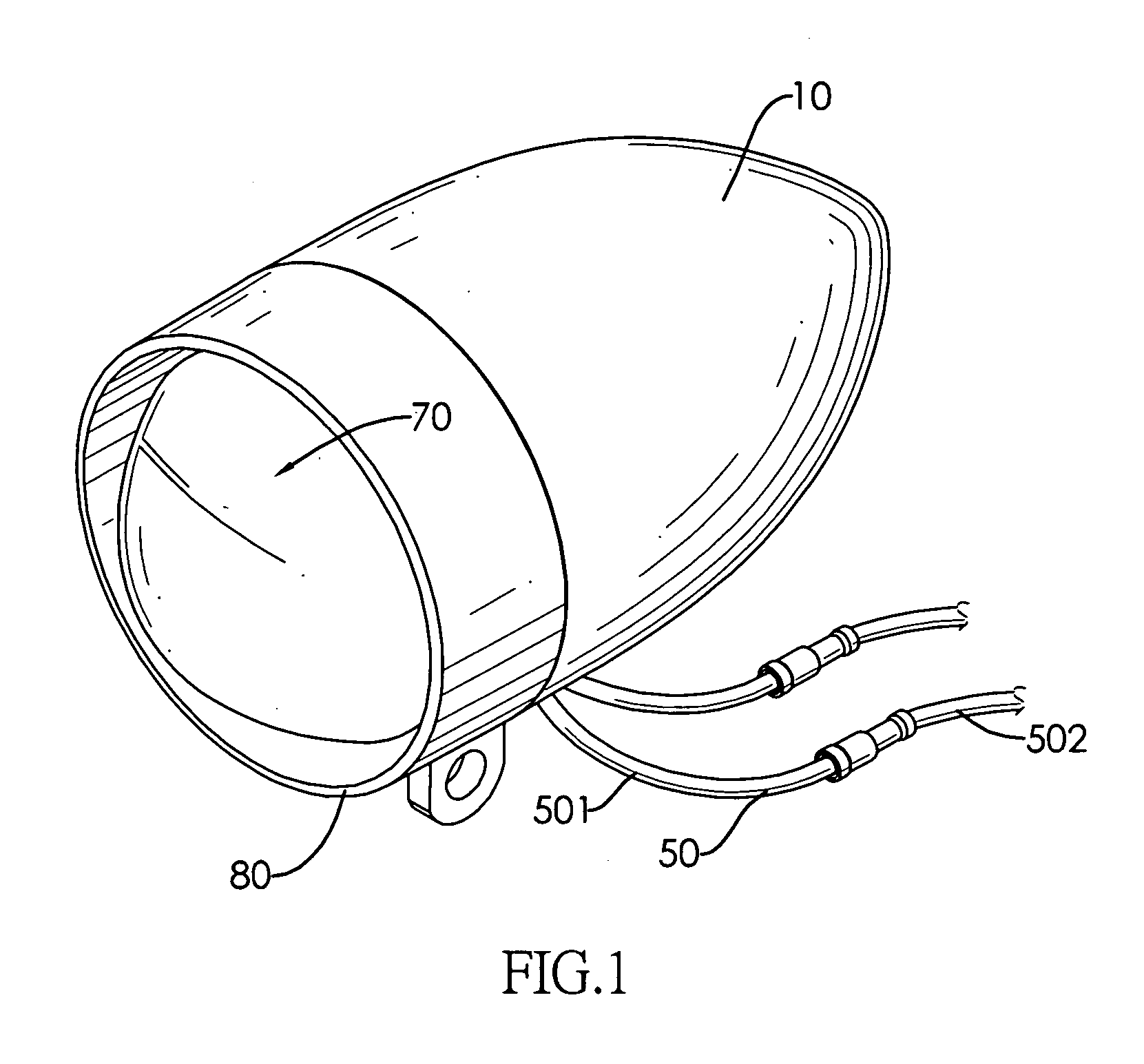
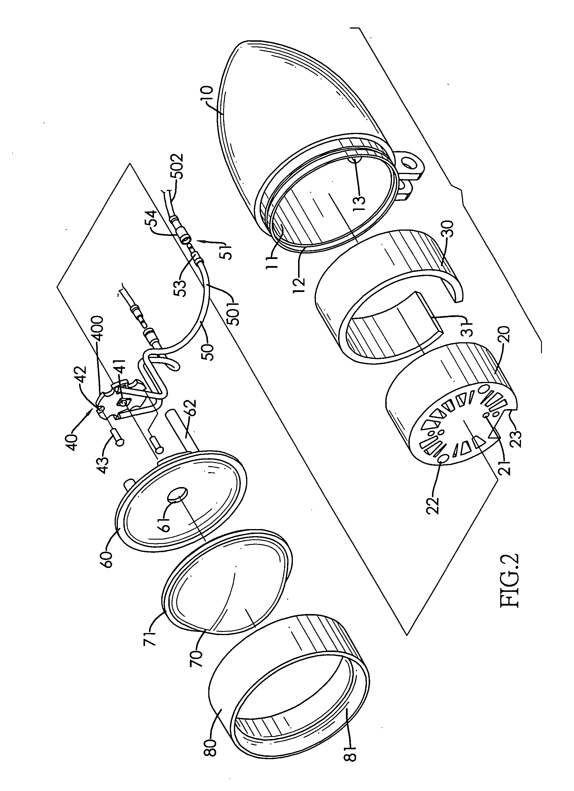
[0014]With reference to FIGS. 1 and 2, a lamp in accordance with the present invention comprises a casing (10), a heat sink (20), a thermal tape (30), an LED module (40), two cables (50), a reflector (60), a convex lens (70) and a mounting collar (80).

[0015]The casing (10) has a chamber (11), a front opening (12) and a cable outlet hole (13). The chamber (11) is defined in the casing (10) and has an inner surface. The front opening (12) is defined through the casing (10) and communicates with the chamber (11). The cable outlet hole (13) is defined through the casing (10) and communicates with the chamber (11).

[0016]The heat sink (20) is mounted in the chamber (11) of the casing (10) and has an outer edge and may further have at least one mounting hole (21), at least one through hole (22) and a cable slot (23). The at least one mounting hole (21) is defined in the heat sink (20) and faces forwards. The at least one through hole (22) is defined through the heat sink (20). The cable sl...


PUM


Abstract

A lamp has a casing, a heat sink, a thermal tape, an LED module, two cables, a convex lens and a mounting collar. The heat sink, thermal tape and LED module are mounted in the casing. The cables are connected to the LED module and each cable has a stationary cable section, a detachable cable section and a cable connector assembly. The cable connector assembly is mounted between the stationary and detachable cable sections and selectively detaches the detachable cable section from the stationary cable section. The convex lens and mounted collar are mounted in the casing. The cable connector assembly facilitates the replacement of the LED module.

Description

BACKGROUND OF THE INVENTION[0001]1. Field of the Invention[0002]The present invention relates to a lamp, and more particularly to a lamp that has LED module and cable connector assemblies, facilitates the replacement of the LED module and lowers a material cost.[0003]2. Description of Related Art[0004]Currently widely used incandescent lamps are gradually being replaced by light emitting diodes (LED) for energy saving and environmental protection purposes because of comparatively lower power consumption and longer lifespan of the LEDs.[0005]A conventional LED lamp has a casing, a shade, a heat sink, a fan and an LED module. The casing has a through hole defined therethrough. The shade is mounted on and covers the casing. The heat sink and fan are mounted in the casing by bolts. The LED module is mounted on the heat sink with a light emitting surface facing the shade. The LED module has cables connected securely thereto and each cable has one end extending out of the through hole of ...

Claims


Application Information

Patent Timeline
IPC IPC(8): F21V29/00
CPCF21V29/00F21Y2115/10F21V29/773F21V5/04F21V17/12F21V17/164F21V27/02
Inventor LIN, BENNY
Owner LIN BENNY
Why Eureka
Try Eureka