

Radio relay station, radio relay method, radio communication system, location management device, radio terminal, and radio communication method
a radio relay and radio communication technology, applied in the field of relaying data, can solve the problems of difficulty in changing the communication frequency, increase the size and cost of the radio relay station, etc., and achieve the effect of reducing processing load and power consumption
- Summary
- Abstract
- Description
- Claims
- Application Information
AI Technical Summary
Benefits of technology
Problems solved by technology
Method used
Image

Examples
first embodiment
[0055]First of all, a radio communication system according to a first embodiment of the present invention is described. Specifically, description is given of (1) Schematic Configuration of Radio Communication System, (2) Configuration of Radio Relay Station, (3) Operation of Radio Relay Station, (4) Advantageous Effects, and (5) Modified Example.
(1) Schematic Configuration of Radio Communication System
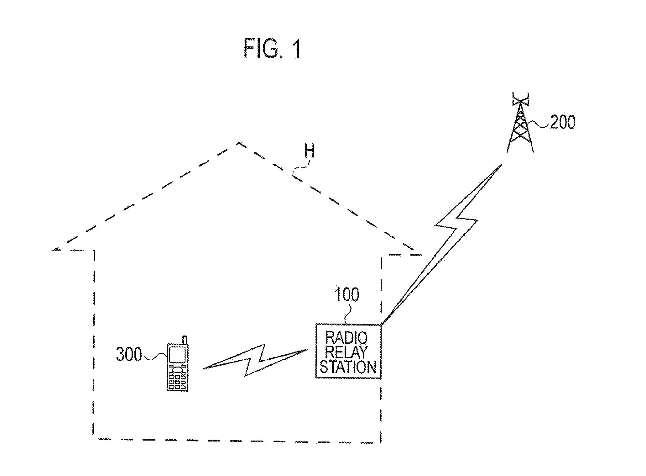
[0056]FIG. 1 is a view showing a schematic configuration of a radio communication system 1 according to the first embodiment.
[0057]As shown in FIG. 1, the radio communication system 1 includes a radio relay station 100, a radio base station 200, and a radio terminal 300. The radiocommunication system 1 has a configuration based on WiMAX (IEEE802.16). In other words, the radio communication system 1 employs the orthogonal frequency-division multiple access (OFDMA) scheme and the time division duplex (TDD) scheme.
[0058]The OFDMA scheme realizes multiple accesses by using multiple subcarr...
first modified example
(5.1) First Modified Example
[0085]The radio relay station 100 is often installed in the cell fringe of the radio base station 200. Hence, a radio wave from the radio base station 200 sometimes fails to reach the radio relay station 100 normally depending on an installation location of the radio relay station 100. In this case, the radio relay station 100 cannot relay data.
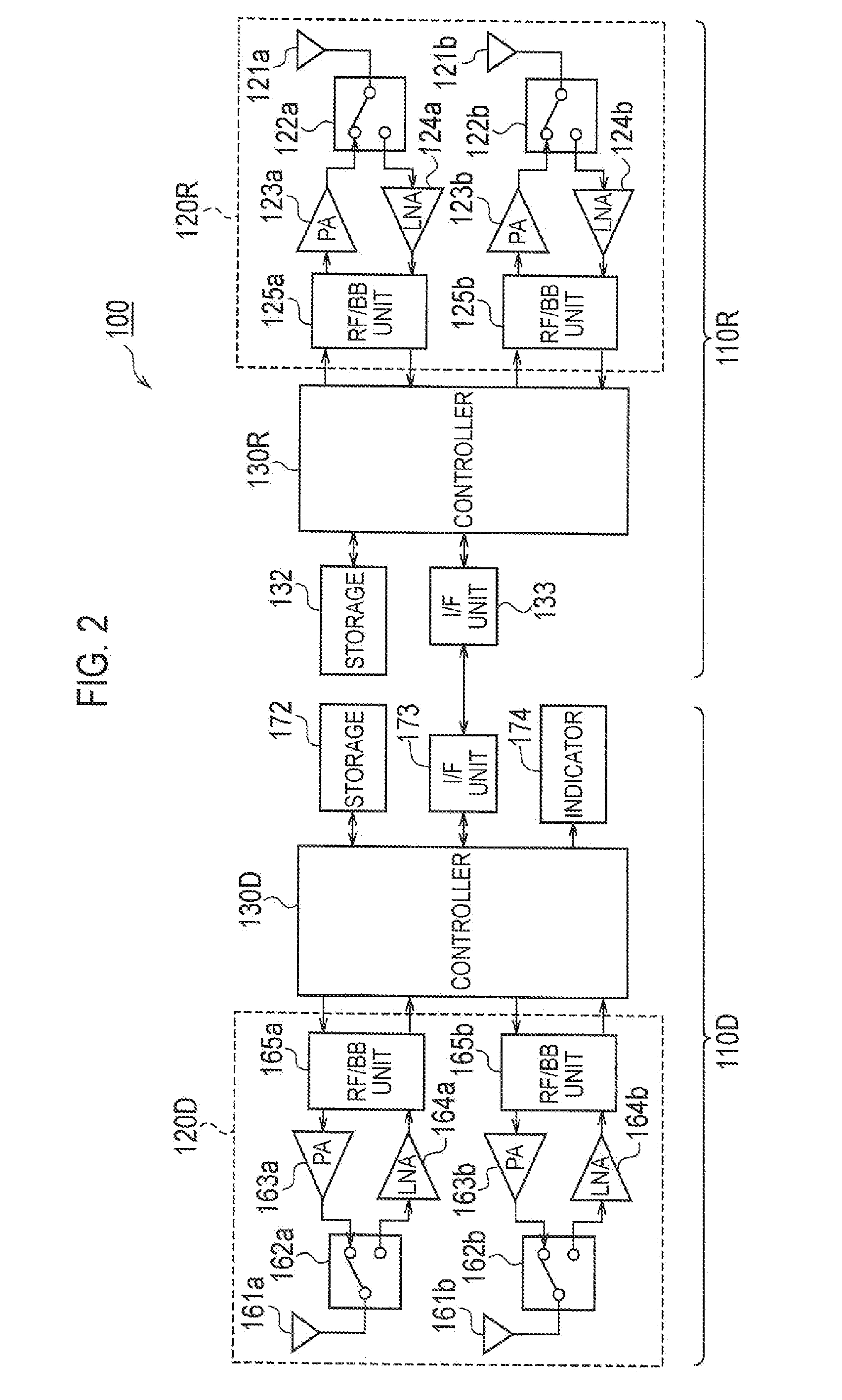
[0086]To address this problem, the radio relay station 100 in a first modified example can be connected to an external antenna unit 190, as shown in FIG. 6. Thereby, the radio relay station 100 can relay data even if a radio wave from the radio base station 200 fails to reach the radio relay station 100 normally.
[0087]The radio relay station 100 according to the first modified example has a connecting terminal to and from which a cable from the external antenna unit 190 is attached and detached. The controller 130D automatically switches the transmission / reception system from the donor-side transceiver 120D to the ...
second modified example
(5.2) Second Modified Example
[0088]As has been described above, a frequency band available for use by the donor-side transceiver 120D and the remote-side transceiver 120R in radio communication in the radio communication system 1 is set in advance. As shown in FIG. 7, for example, a frequency band of 30 MHz is available, and is equally divided into three communication frequencies F1 to F3.
[0089]In a second modified example, the donor-side transceiver 120D performs radio communication with the radio base station 200 by not using the central communication frequency F3 but using the communication frequency F1; the remote-side transceiver 120R performs radio communication with the radio terminal 300 by not using the central communication frequency F3 but using the communication frequency F2. This secures an interval between the communication frequencies respectively used by the remote-side transceiver 120R and the donor-side transceiver 120D, thereby further reducing the influence of in...
PUM
 Abstract
Description
Claims
Application Information