

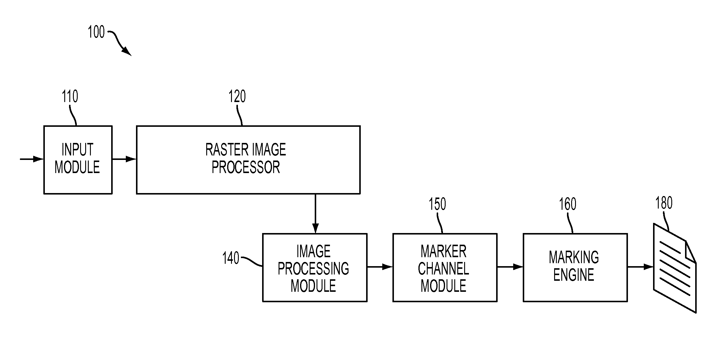
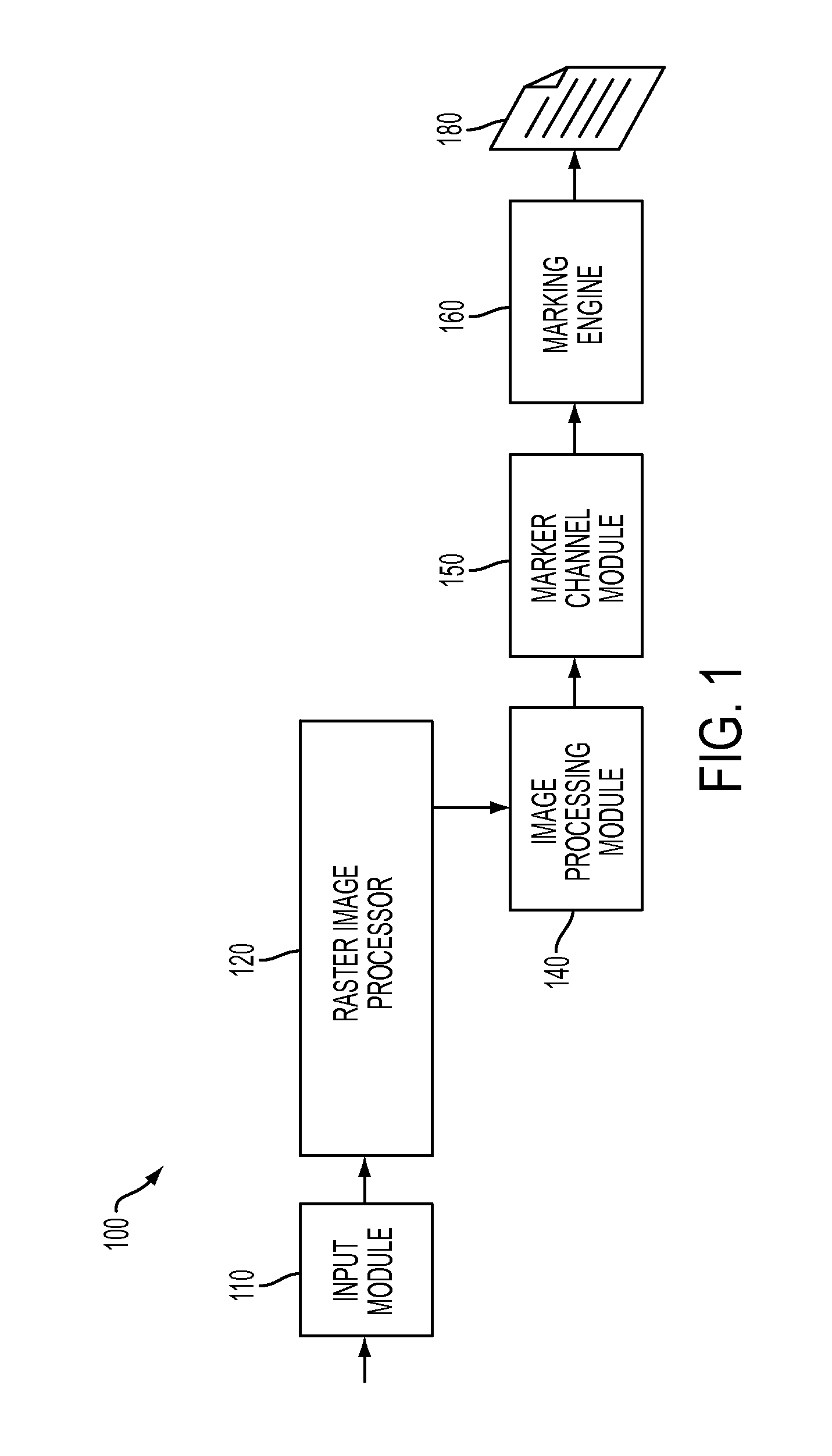
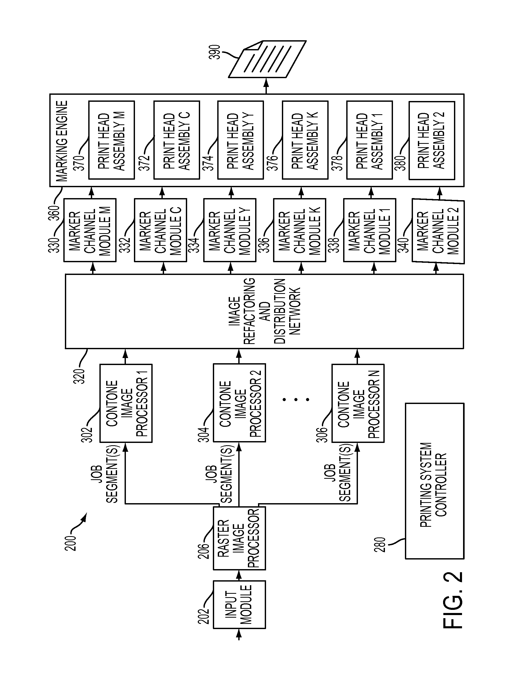
Distributed data flow for page parallel image processing within printing systems
a printing system and data flow technology, applied in the field of data processing within the printing system, can solve the problems of increasing the cost/performance trade-off between each of these functions, introducing new complexity and problems associated with partitioning the data flow, coordination, communication,
- Summary
- Abstract
- Description
- Claims
- Application Information
AI Technical Summary
Benefits of technology
Problems solved by technology
Method used
Image

Examples
Embodiment Construction
[0012]The following definitions apply to each term as utilized within this disclosure. It is to be appreciated that if more than one interpretation is indentified, the definition relates to the interpretation with the broadest scope.
[0013]“Job” Information sent to a printing system that describes a desired output. This information is in the form of a Page Description Language (PDL) such as Postscript, PDF, PCL, IPDS, etc. Anything that a printer accepts and prints can be considered to be a PDL.
[0014]“Job Segment” Subdivision of the job identified and communicated or processed independently for the convenience or efficiency of the printing system. Each job segment may be comprised of one or more lower level subdivisions, such as Logical Pages or Logical Sheets, and if so comprised, these lower level subdivisions may or may not have a correlation to how they are sequenced, grouped or described in the input job or how they will appear on the final marked output. Job Segments are expres...
PUM
 Abstract
Description
Claims
Application Information