Method and system for uplink beamforming calibration in a multi-antenna wireless communication system

a multi-antenna wireless communication and beamforming technology, applied in the field of communication systems, can solve problems such as time-varying signal quality

Active Publication Date: 2011-08-11
AVAGO TECH INT SALES PTE LTD
View PDF25 Cites 93 Cited by
  • Summary
  • Abstract
  • Description
  • Claims
  • Application Information

AI Technical Summary

Benefits of technology

[0009]These and other advantages, aspects and novel features of the present invention, as well as details of an illustrated embodiment thereof, will be more fully understood from the following description and drawings.

Problems solved by technology

Signals transmitted over communication channels may exhibit co-channel interference, path loss, shadowing, and / or multipath fading, which directly affect the communicated signals and result in time-varying signal quality such as time-varying signal to interference plus noise power ratio (SINR).

Method used


Image

  • Method and system for uplink beamforming calibration in a multi-antenna wireless communication system
  • Method and system for uplink beamforming calibration in a multi-antenna wireless communication system
  • Method and system for uplink beamforming calibration in a multi-antenna wireless communication system

Examples


Embodiment Construction

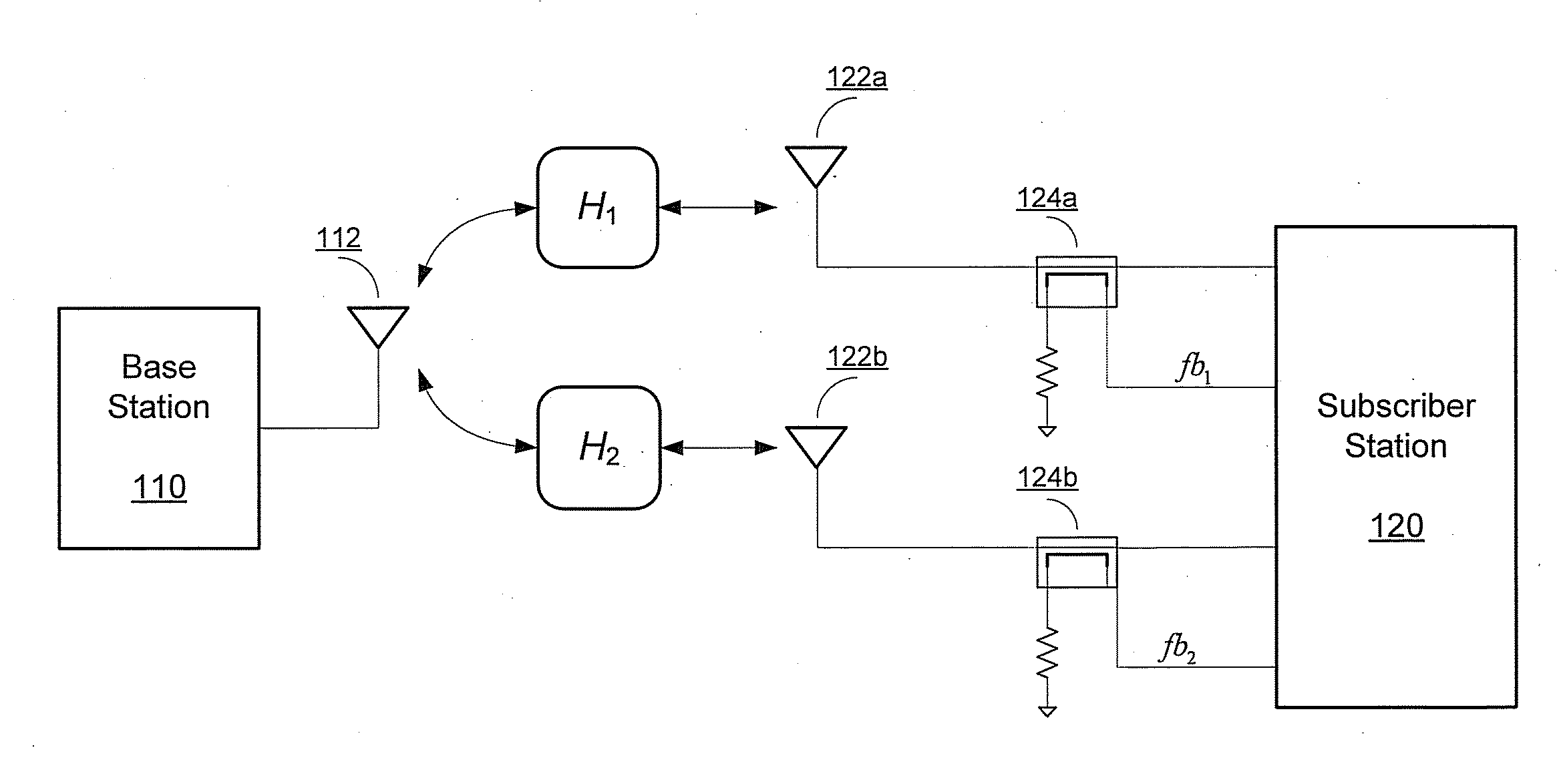
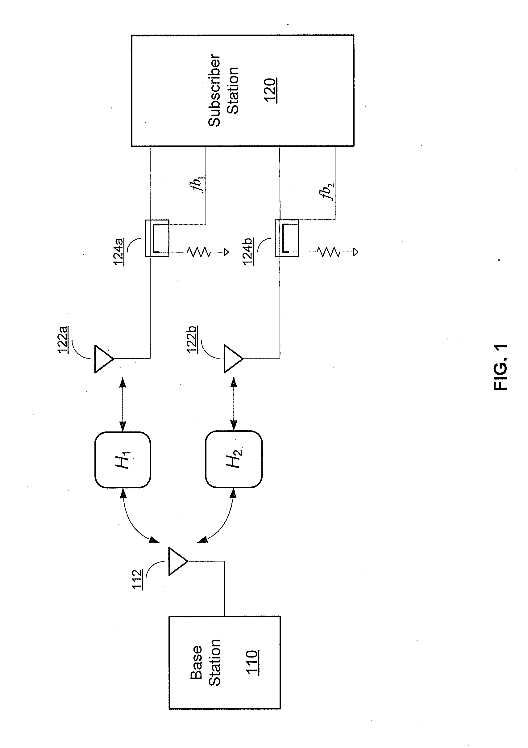
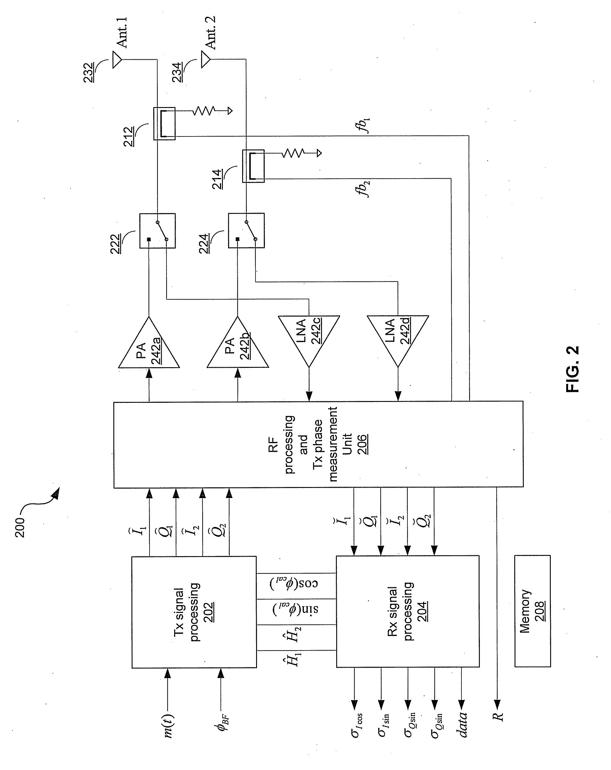
[0020]Certain embodiments of the invention may be found in a method and system for uplink beamforming calibration in a multi-antenna communication system. In various embodiments of the invention, a wireless transceiver, comprising a transmitter, a receiver, and an antenna array, may be operable to determine a desired time-varying transmit phase relationship between a plurality of antennas based on radio frequency signals received by the plurality of antennas, and a phase difference in the receiver path and a phase differences between the transmitter path to each of the plurality of antennas.

[0021]The received radio frequency signals are communicated from one or more antennas of a base station. Two or more of the plurality of antennas, and corresponding transmit power levels may be selected, based upon characteristics determined from the received RF signals. An exemplary characteristic is receive signal strength, commonly referred to as RSSI. The wireless transceiver may transmit RF ...


PUM


Abstract

A wireless transceiver, comprising a transmitter, a receiver and a plurality of antennas, determines transmit phase relationship between at least two of antennas based on radio frequency (RF) signals received via the at least two antennas from one or more antennas of a base station. RF signals are transmitted via the at least two antennas utilizing the determined transmit phase relationship. The receiver is calibrated based on receiver performance determined from the received RF signals for subsequent reception of RF signals. The transmit phase relationship is dynamically adjusted based on the transmit RF measurements and the determined receiver performance. Transmit channel qualities are determined for each transmit antenna based on the transmit RF measurements and the dynamically adjusted transmit phase relationship. Transmit antennas are dynamically selected based on the adjusted transmit phase relationship, the characterized transmit channel qualities and the determined receiver performance for subsequent transmission to the base station.

Description

CROSS-REFERENCE TO RELATED APPLICATIONS / INCORPORATION BY REFERENCE[0001]This patent application makes reference to, claims priority to and claims the benefit from U.S. Provisional Patent Application Ser. No. 61 / 302,214 (Attorney Docket No. 23832US01, BCM157P) filed on Feb. 8, 2010.[0002]This patent application also makes reference to United States application Ser. No. ______ (Attorney Docket No. 23716US02) filed on even date herewith.[0003]Each of the above stated applications is hereby incorporated herein by reference in its entirety.FIELD OF THE INVENTION[0004]Certain embodiments of the invention relate to communication systems. More specifically, certain embodiments of the invention relate to a method and system for uplink beamforming calibration in multi-antenna communication system.BACKGROUND OF THE INVENTION[0005]Wireless communication systems may be implemented utilizing various access techniques such as, for example, code division multiple access (CDMA), time division multip...

Claims


Application Information

Patent Timeline
Patent Type & Authority Applications(United States)
IPC IPC(8): H04W24/00H04B17/40
CPCH01Q3/2647H04B7/0682H04B17/309H04W72/02H04B17/12H04B7/0691H04B17/11H04B17/29H04B7/0413H04B7/0617H04B1/58
Inventor DAKSHINAMURTHY, SRIRAMANLORENZ, ROBERT GUSTAV
Owner AVAGO TECH INT SALES PTE LTD
Why Eureka
Try Eureka